DIY Wood-workbench

In the parallel universe :D, the other members were re-working the legs and making a connector sort of structure which can be plugged in the 3-inch tabletop.

The work involved use of a multitude of tools, including a circular saw, hand saw and chisel to finally convert the cuboid legs into the requisite form.

Here is the final output of the day’s work:

and here is the journey. We were also joined by the other members of the community who helped in the process.

We started the day to plane the legs of the wood. @VirenVaz got his own planer today. Its indeed a fascinating tool which comes in various shapes, sizes and forms.
Balancing is most important when you want to target a certain section of wood area which you are planeing. The spacing and positioning of the front and back leg, the way you hold the tool and the body movements are all very important factor while using this.
There can be risk of injury and the job will be don poorly when the form is not correct.

Thereafter, we clamped it to make the necessary cut.


Joy after finishing milestones :slight_smile: @jtd @VirenVaz

Meanwhile, @jtd discovered a hole inside one the wooden pieces and we were surprised to see the depth of it. Here you can see the wire coming out from the other end.

How do you think the hole gets popped up in this piece of wood?

Now, its the difficult part. To make the straight cut using a hand saw and remove the center piece using a chisel.


customary selfie of the day!

Finally, we completed all the 4 legs for the workbench. It does look pretty, isn’t it?

5 Likes

Day 3 ( 23 Aug 2019 Fri)

The wood arrived in the afternoon. We split the longer one into 4 ft each. We got two different colors and sandwich the logs to give an aesthetically pleasing texture.
Circular saw and hand saw were used to get the desired length after the measurements.

As you can see above, the logs are ready to be glued. Not really, on placing it side by side, there are gaps which need to be fixed so that the adhesive can be applied effectively.

For ensuring that, we need to plane the specific region from the side and repeat the process iteratively.

Gaps

Finally, after a lot of iterations, we finished the planeing. Then we applied adhesive on sides.

Here I would like to mention about an interesting detour. @jtd and @VirenVaz were also working on a mechanism which can hold the big wooden pieces together. One way to go about it to have a big clamp to hold these things, but we don’t have that here. The other interesting frugal technique is to use the wedge mechanism to make a clamp.


Finally, we kept a heavy object on top of it and called it a day.


Overall, it was indeed an insightful experience especially learning about adhesives, clamps and working with different woods.

Chisel stand.

The slots were cut using the huge chop saw in the workshop. I then had to widen each cut. I used the chisel initially, and ended up with one side cracking off the piece. A brass nail and wood glue set it right. I then switched to the 18" hand saw to expand the slots. To fix the slotted piece to the rear cleat piece I used two self threading metal CSK minus head screws type AB thread, length 1.5".

A minus head screw has a single slot to hold the screw driver bit and requires one to maintain a plumb vertical position while driving the screw. Consequently one has to exert substantial down wards pressure to prevent the screwdriver from jumping out and shredding the head. I used the power drill machine with a minus bit to ease the job. Unfortunately in an attempt to make the head flush with the ply I over torqued the screw and caused it to snap. Extracting a broken screw from wood is an onerous task. So I had to drill a fresh set of holes. I changed plans and instead of screws, used nails and stuck the two pieces together using poly vinyl acetate glue, more popularly known as Fevicol.

Note for self: Buy a battery powered driver and use + head screws (also known as philips head).

Since the holder is overhanging, the weight of the chisels will pull the stand down, but also forward. It is possible that the stand will topple, a very dangerous situation with sharp edged and heavy objects. I therefore added a small piece of wood that acts as a clamp, preventing any possibility of toppling. I used two small 1" tack nails and PVA glue.
Thinking about the ergonomics and safety, I thought that the chisel might snag if one twists and pulls it out, thereby dislodging the entire stand and causing an accident. This would happen if one used only one hand. However I could not cause such a snag despite several attempts.

Day 4
Today’s task requires both patience and accuracy. We need to cut so that the legs can fit on to the base. Since all the 4 legs are not exactly accurate, we have to customize the holes in the base according to the respective legs.


The first two holes were done using hand tools- slowly and steadily. Using a hand saw, chisel and hammer to make series of cut and then to remove the corner end .After that to make a deep cuboid shape cut of around 6 inches deep in the interior. Lastly, the interior walls needed to be smoothed so that the legs can fit in- its should neither be too tight not too loose.
Making the cut with the saw and working to remove the outside piece

!
Here you can see series of cut. Later on you can use the chisel to remove the pieces one by one.
IMG_20190826_123248004|666x500
When we were left with the final slot, the team become curious to try another method to achieve the same. We used the industrial drill machine to help us with the process. Here, you can see the team experimenting with both electric circulars saw to make a series of cut initially, and later on using a drill press to make the interior cuboid.


Overall, we managed to complete the slots at the end of day 4.

We were joined by Panchami and she got inspired by Viren’s wooden puzzle hence decided to make one for herself


1 Like

Day 5

The first half of the day went mostly to plane all the six faces of the table.

In the second half, the necessary adjustments were made so that the legs fit in the grove properly. This indeed is a meticulous job and requires a lot of patience, estimation, and skill. Finally, when the legs were plugged in, the extra part on top was removed and smoothed.


We had some fun towards the end.


We would sincerely like to express the deepest gratitude to all the members who were involved in the project. Viren for being a superb mentor, Puneet for seeding the idea , Jude, GN, KS, VK, Ashish, Manoj, Shashank, Deborah, DP, Anil Sir, Cosmetic Staff, technical team, and all the other communities members for contributing in various capacities towards the completion of the project.

What’s next?

  • Use wood putty to fill in the cracks in the workbench - around the legs
  • Sand it to a smooth finish
  • Attach the leg vise, make dog holes
6 Likes

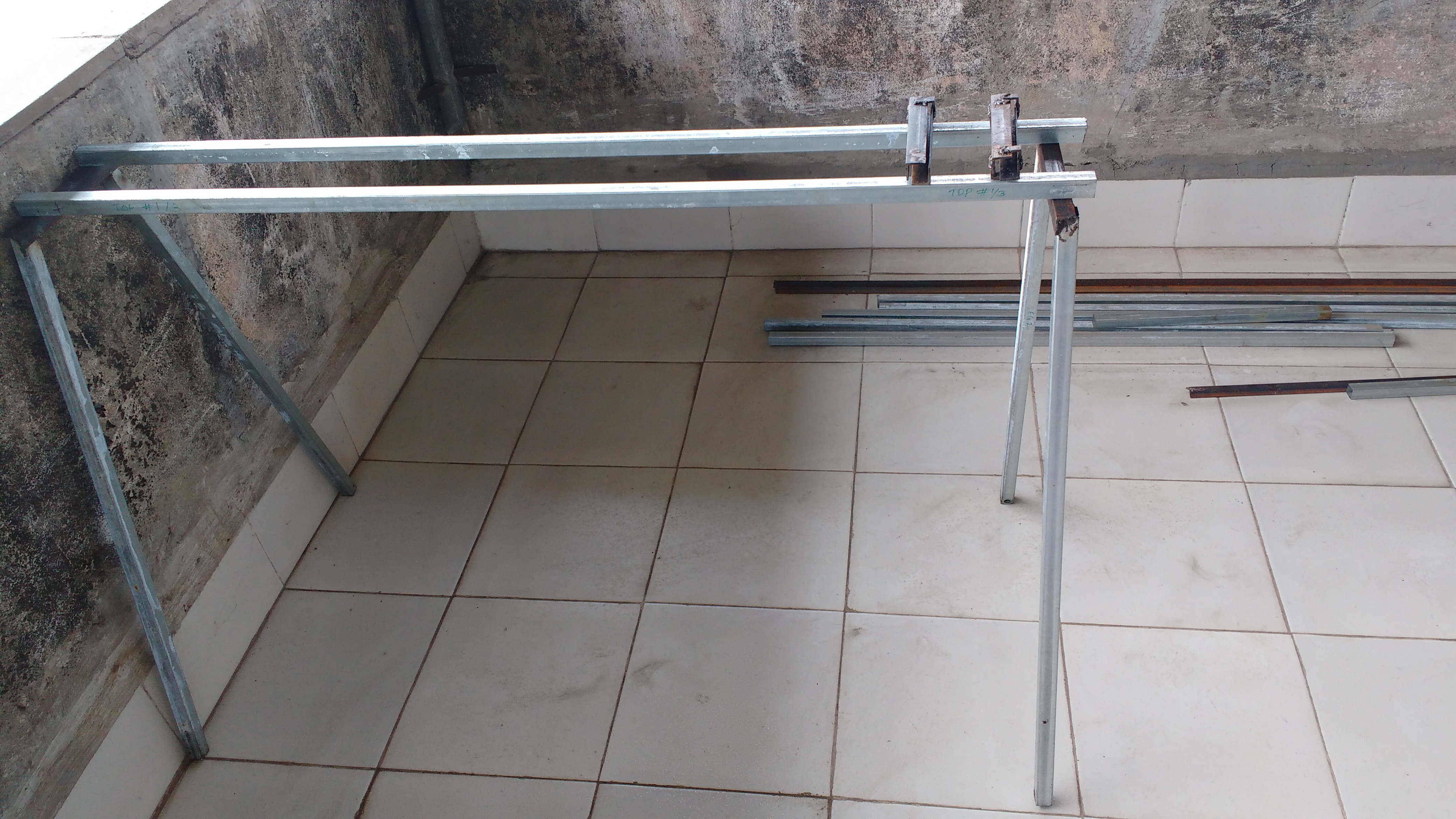
I felt the need for a saw horse cum welding table. @Pneb wanted the working height different from what I need, the height has to be adjustable. Since the height has to be adjustable, might as well make it sufficiently adjustable to work standing or seated. Talk of feature creep!
Some images from the ongoing endeavor:
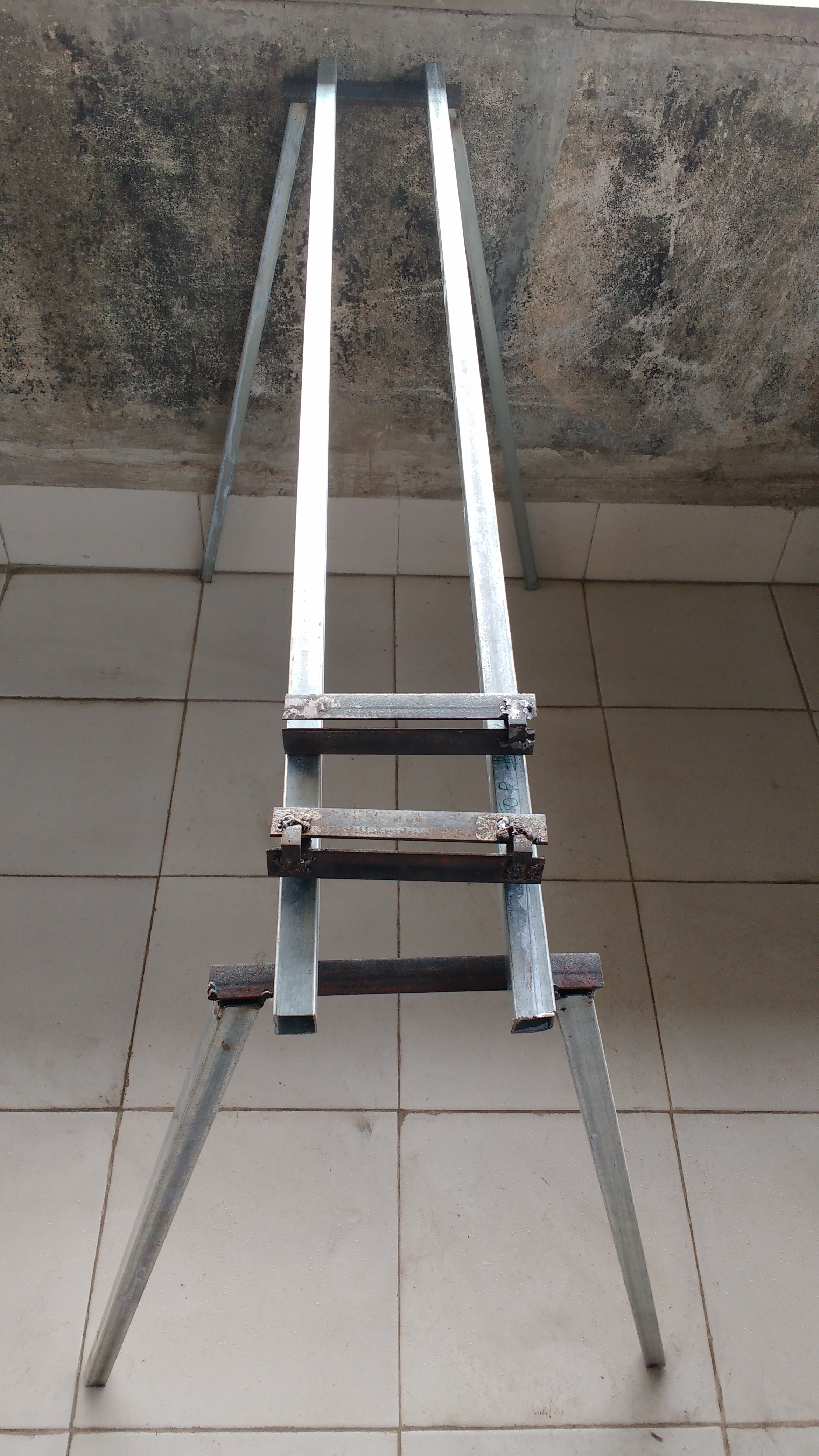
Legs with an angled cut of $11^o$ welded to the top.

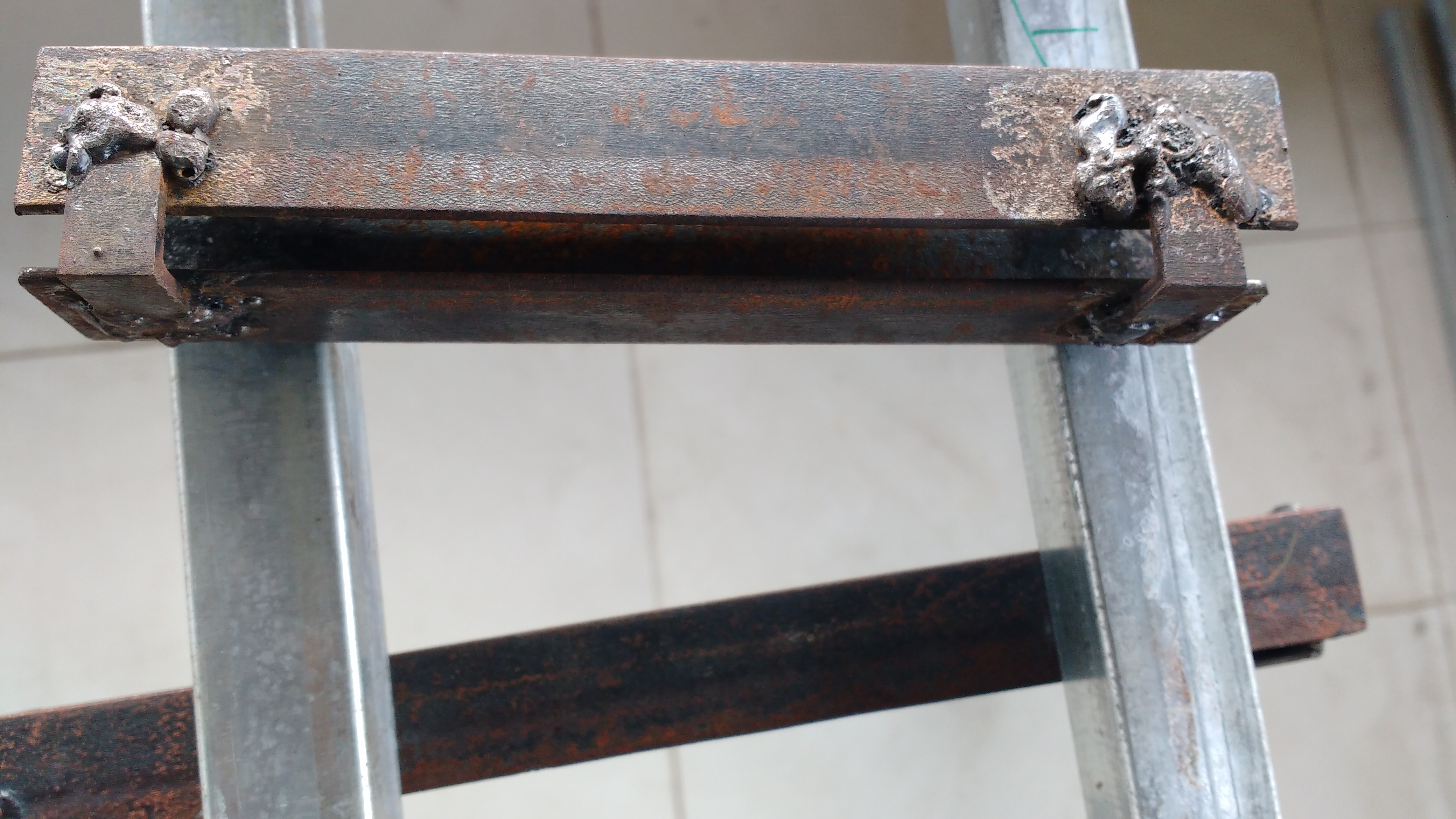
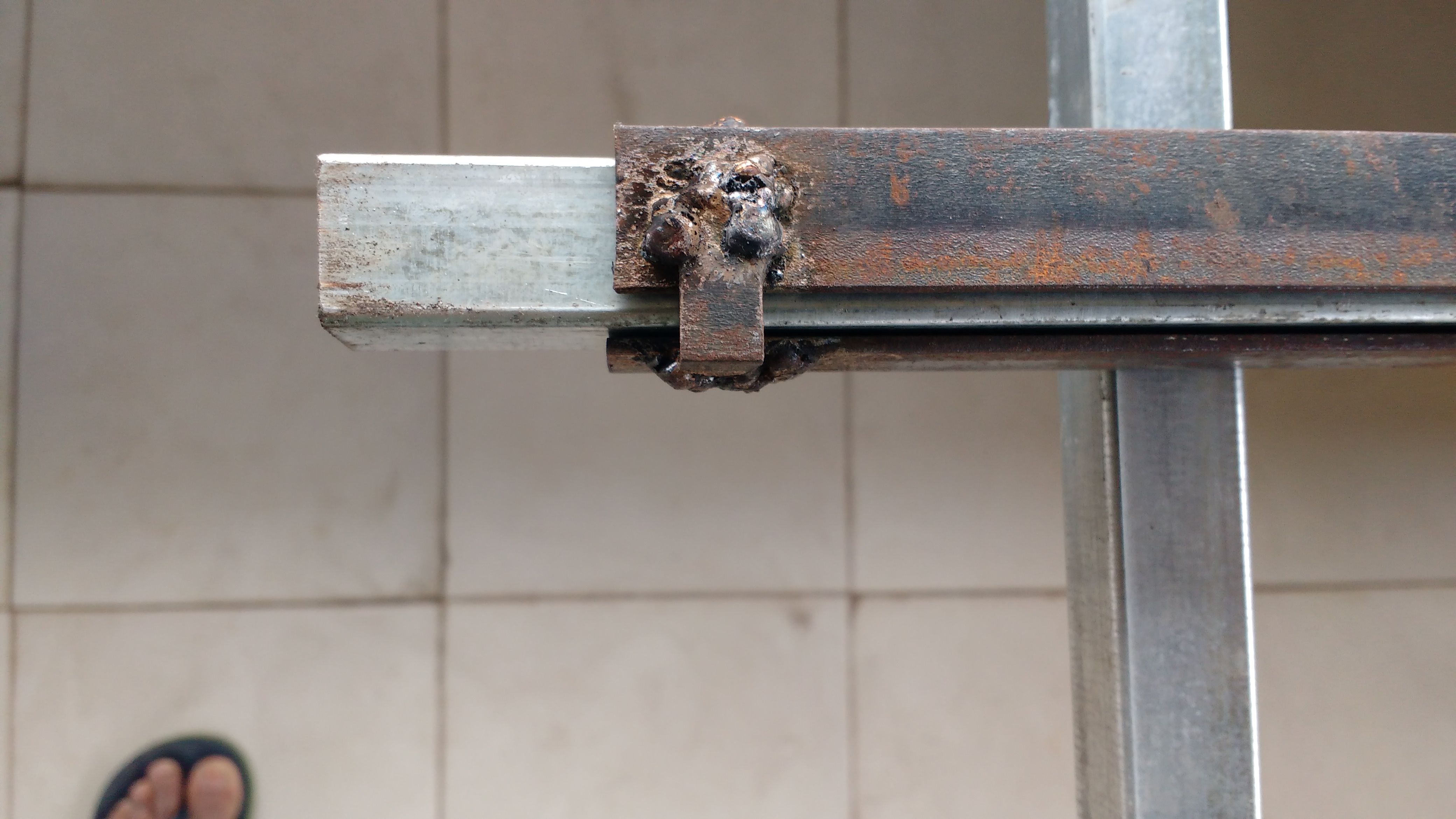
Socket for adjustable height. Ugly welds due to lack of skill, but functional


Socket with sliding section.

Four of these will be used, 2 on each leg frame. Top frame will be fixed to the sliding section.
Four sockets are used to provide maximum stability. However that makes adjustment difficult if you are alone. Ideally a crank mechanism…feature creep again!
Notice the play at the end of the video? this will make the top shake approx 2 mm. The gap between slide and socket was created by wrapping some news paper around the slide - 3 layers. Which makes six layers on two opposite faces. Gap might be reduced by using only 2 layers in the rest of the sockets.

2 Likes

Weld on the underside of the saw horse

2 Likes

I think it might have been more practical to create a second height adjusting platform, with dogs to secure the saw frame.

By combining them or fiddling with a stable ‘horse’ (just couldn’t resist it :smile:), a structure of good stability is being compromised.

A practical, although maybe more expensive in theory, very stable height adjusting platform for heavy duty work could be jerry rigged from an automobile hydraulic hand lift.

2 Likes

Great idea . (The bot wants me to verbose - 20 characters )

Rs. 900 to 2200/- . I will need two of these

Why two? Erect a horizontal platform on the lift vertex, and the saw horse can be dogged to it.

1 Like

Ok. That should work too.
I wanted to avoid dogging, which would require my original socket arrangement, and instead just use two hydraulic jacks.
Come to think of it one would be less cumbersome than two jacks.

1 Like

I realised that I don’t actually know the form factor of the lifts you found. Tyre puncture repairers usually use a trolley, which was in my mind when I commented. But there is also a simpler plain cylinder type. I haven’t checked the prices.

Anyhow, whichever is used, it is essential to have a single lever, so that the platform rises horizontally in a single action. I suspect that trying to make this happen with two (or four) jacks is going to be very, maybe unnecessarily, difficult.

1 Like

Turns out that the car hydraulic jacks have limited vertical displacement of 12 to 16 cm. All vehicle jacks have this limit on displacement. I require a isplacement of approx 45cm.

Nonetheless an excellent, low cost and universally available method to make a lifting mechanism.

2 Likes

That is nearly half a meter. Are you saying the difference in ergonomic working height for two persons is so huge?

2 Likes

The difference for two persons is merely 10cm. But we need to work both standing and seated. Therefore the height varies from 75cm ± 10cm to 135cm ± 10cm.

2 Likes

I also checked PA speaker stands. Cost is reasonable -1900 to 3500 and they fit the height adjustment range, but will not be stable enough.

1 Like

I think a single cylinder car jack is probably about 20cm high with a throw of around 10cm. Together with a sturdy fixed platform, within another 10cm. So, two such adjustable platforms, 60cm total. Still cheap, stackable, and likely to be very sturdy, yet straightforward to build. And it gives you what you need, in straight steps of 30cm.

Which also means, you can stack them up against a wall when not in use, if you standardise each unit (2 lifts and the saw horse) to 30cm.


Top frame for saw horse is finally done. Today I am going to add the adjustable height pieces and complete the table. Additional cross members will be added too.
Welding the 17 gauge galvanised square sections is proving to be quite problematic. Firstly the arc burns the galvanised zinc, preventing the weld puddle from welding the two pieces. Next holding the weld rod for even a fraction of a sec longer burns the section. Hence I changed the support for the legs from square section to 2mm (14 swg) x 25mm L angle (the rusty looking strips, it being easier to weld. 2mm thick material welds ok with 2.5mm welding rods. Hereafter I will use a thicker section and ungalvanised. Ungalvanised means I will have to paint to prevent rusting.
Sourcing thicker square sections will be more difficult. It will also increase costs and weight.