2 Likes
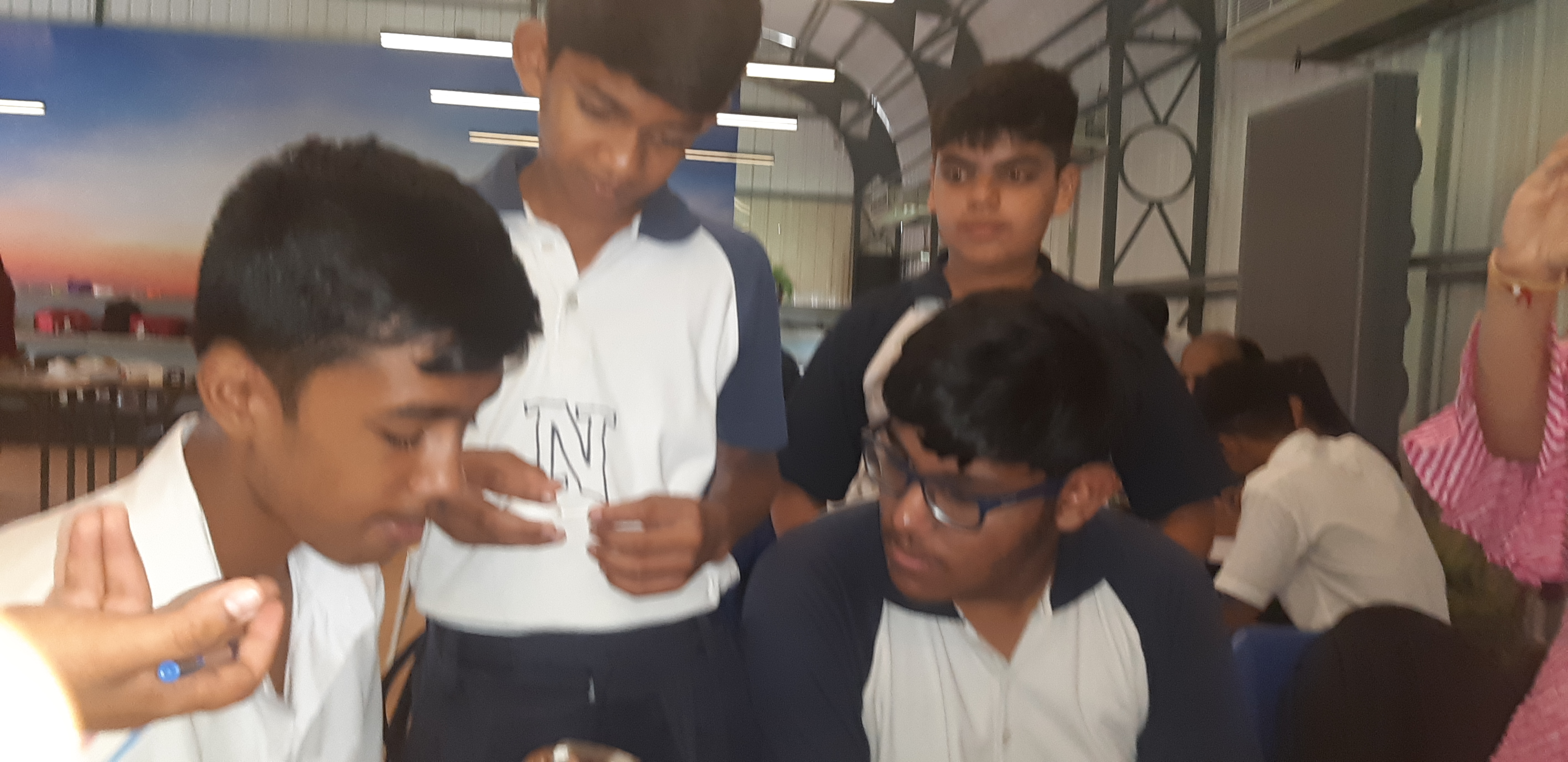
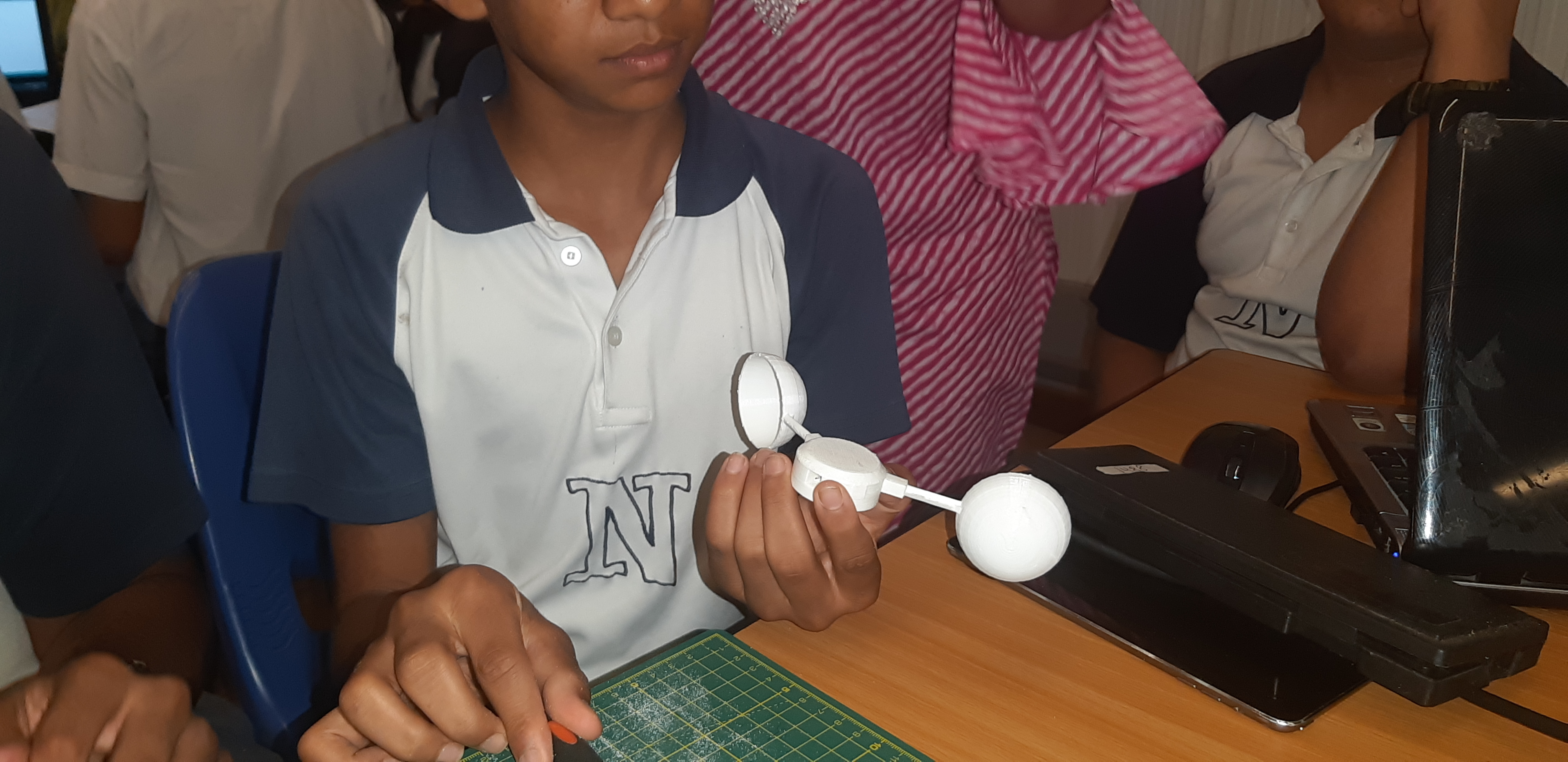
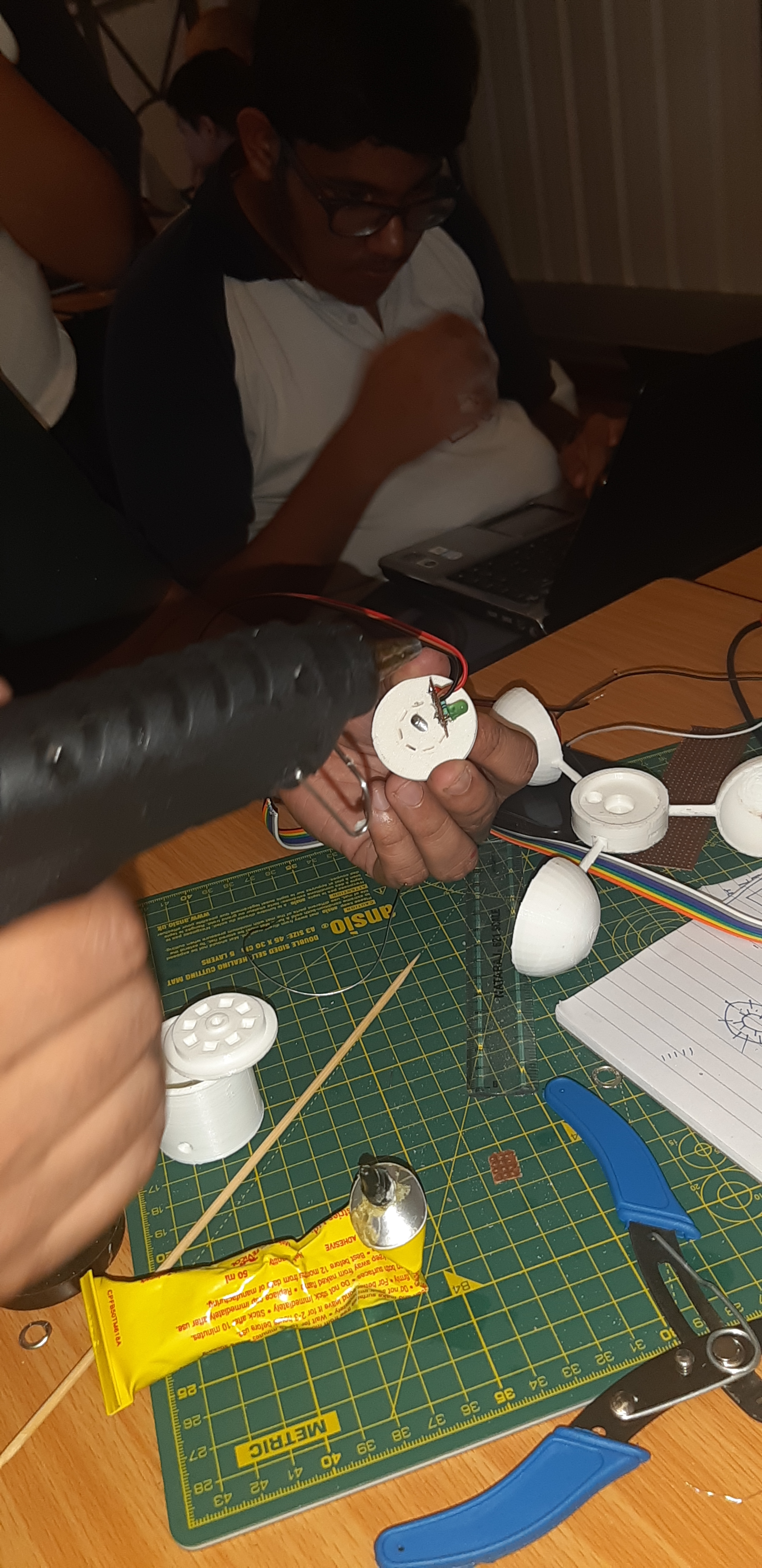
Today’s day started with the knowledge more focused on the practical aspect of designing a anemometer. Which included first the filing of the 3d parts of the anemoneter with a filler so that it can easily fit and can be compiled
2 Likes
2 Likes
Team work
Uploading: 20190724_090507.jpg…
@ananya13 @tanmay @divyansh @rahgav @Kavin @Ankita1 sharma
1 Like
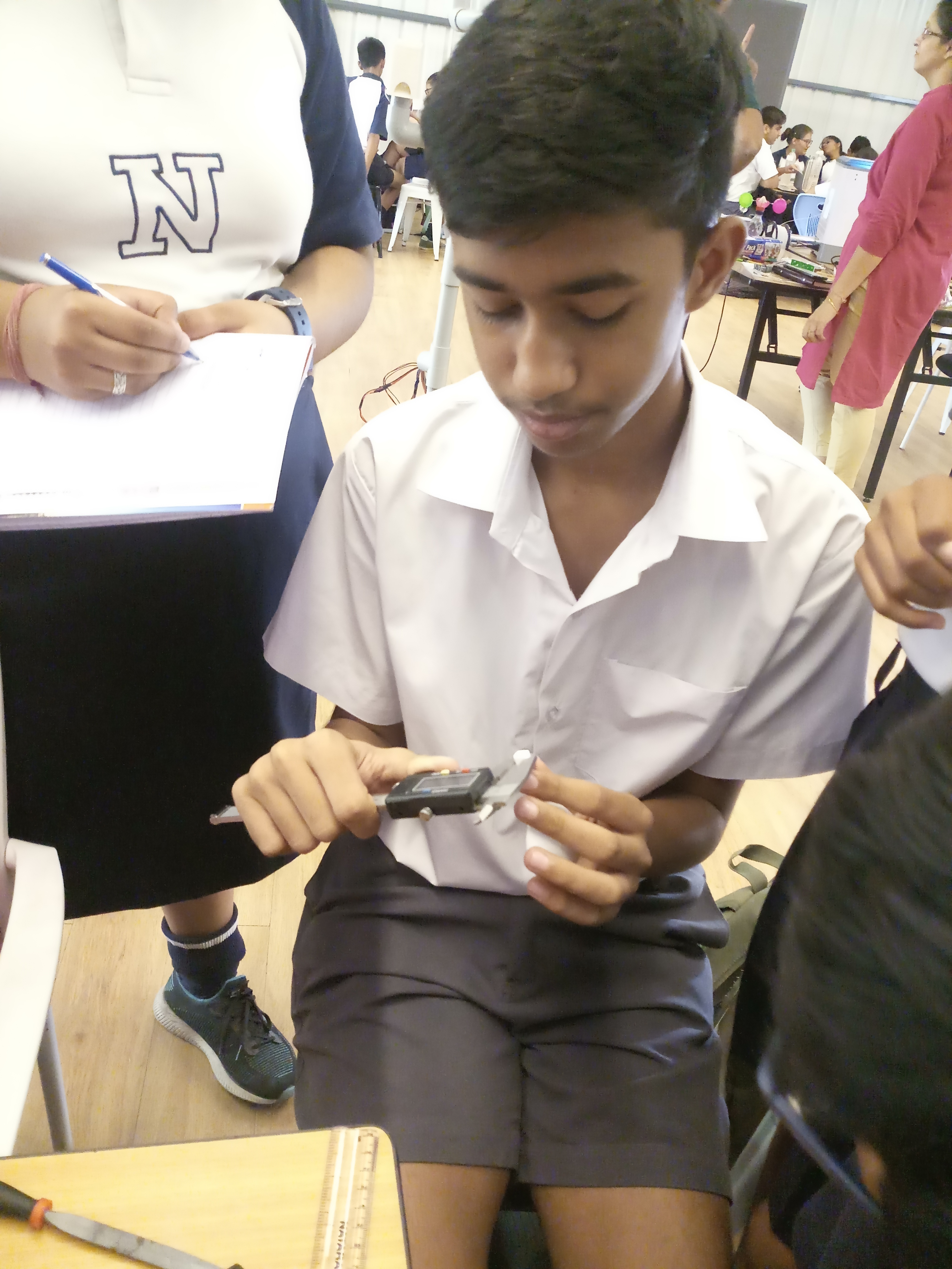
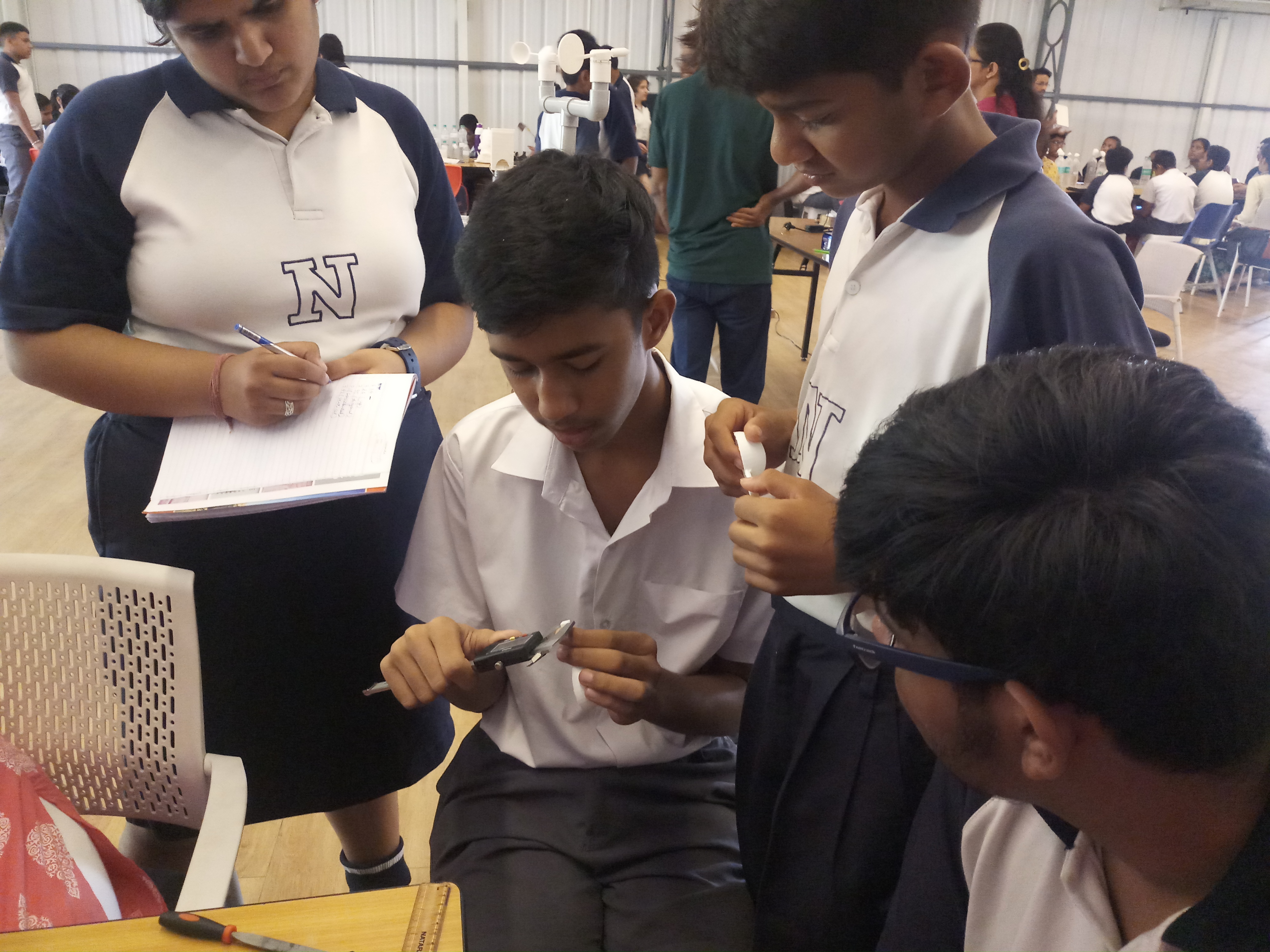
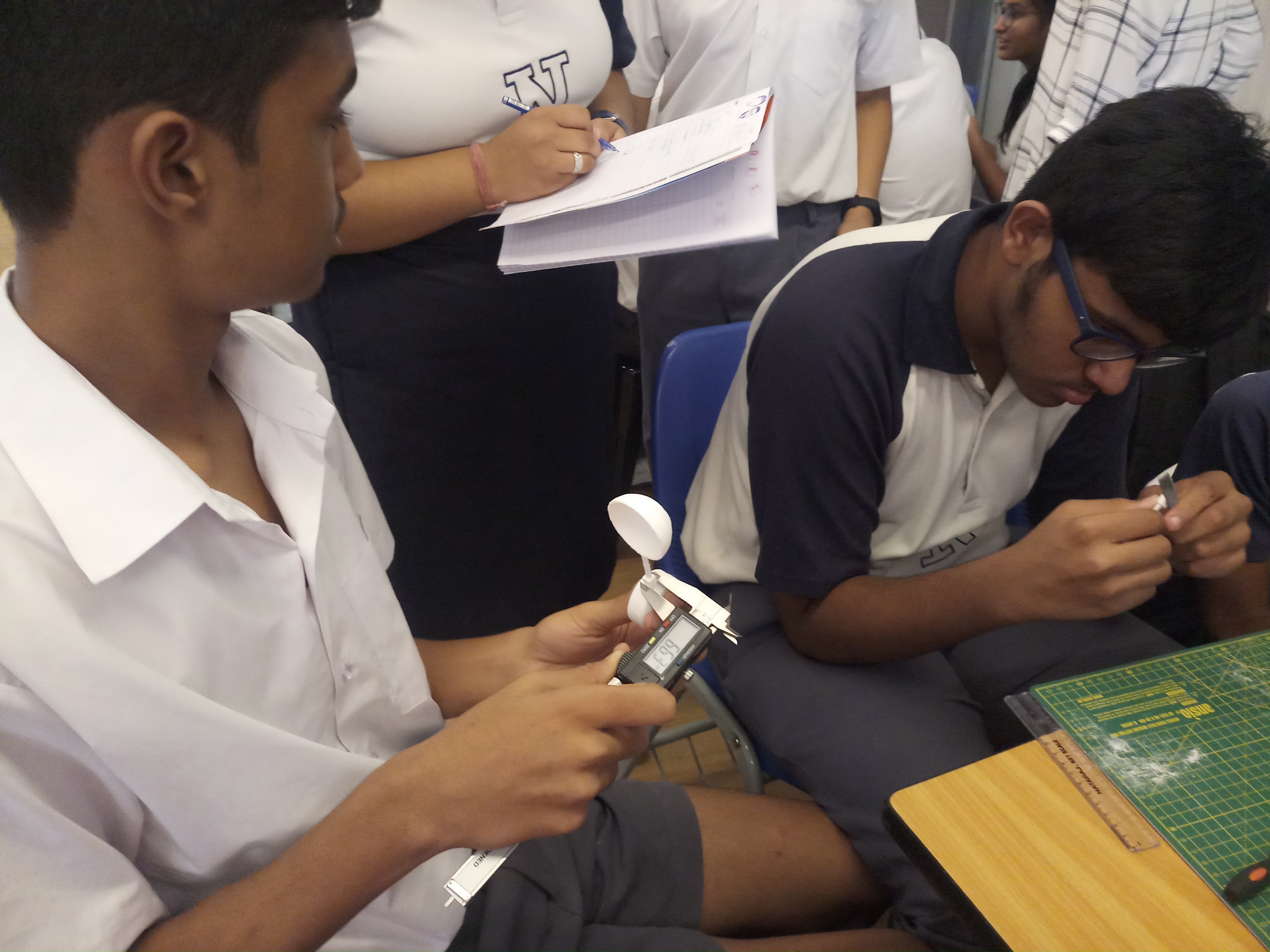
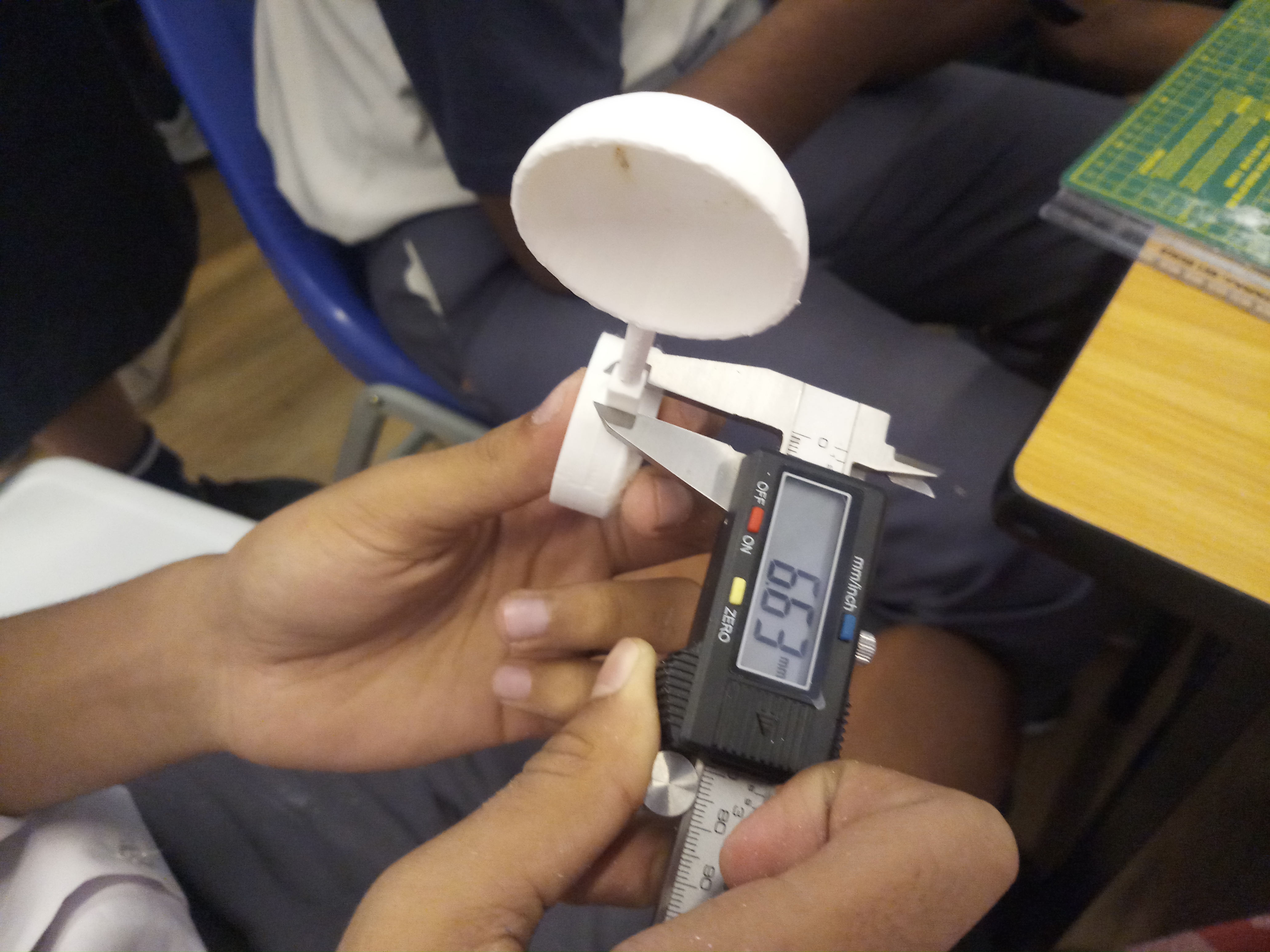
In order to be more accurate for the measurement the more advanced technique which the students used is Vernier caliper which has not only simplified the work of filling but also minimizing the possibilityof error.
2 Likes
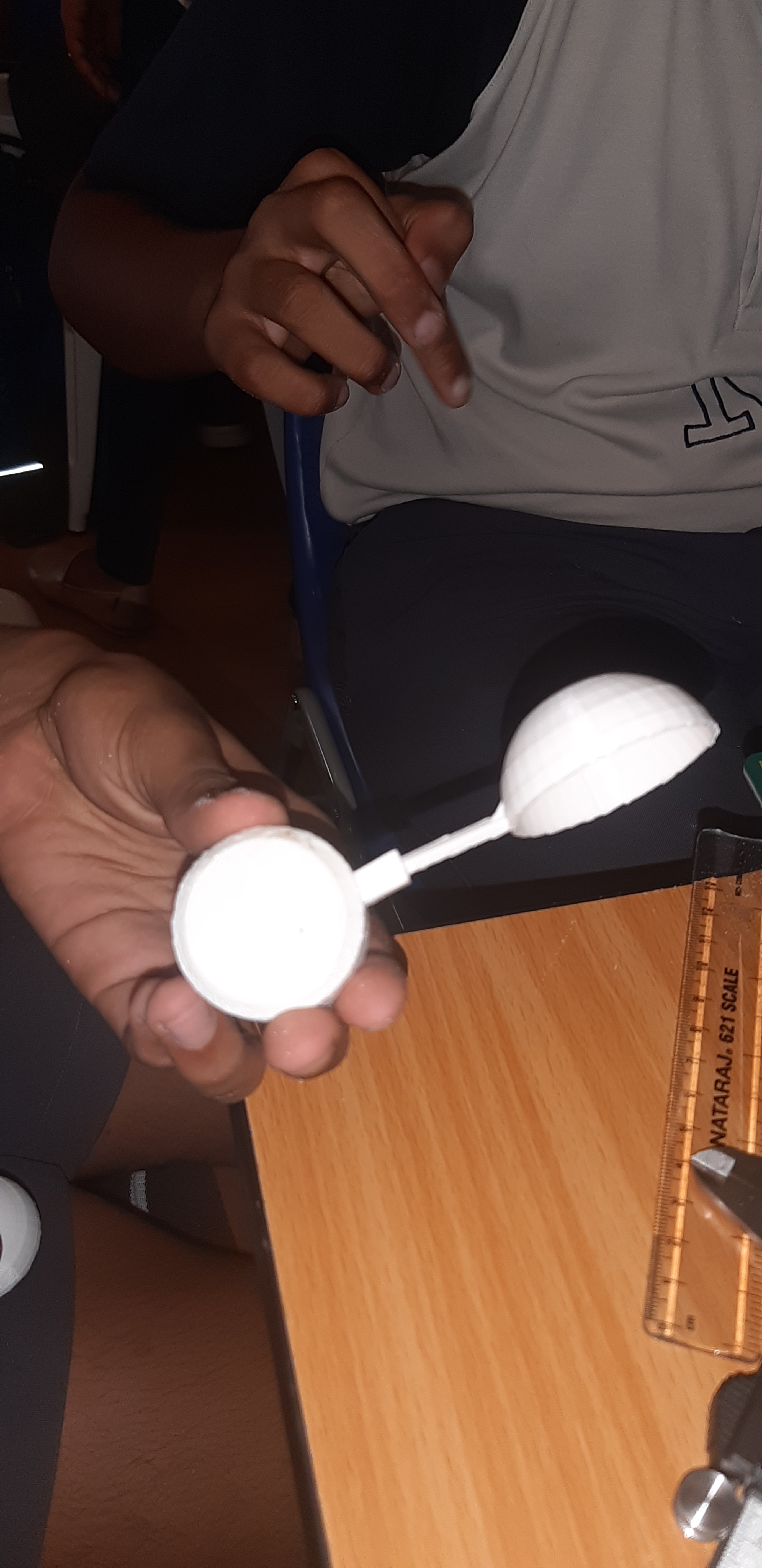
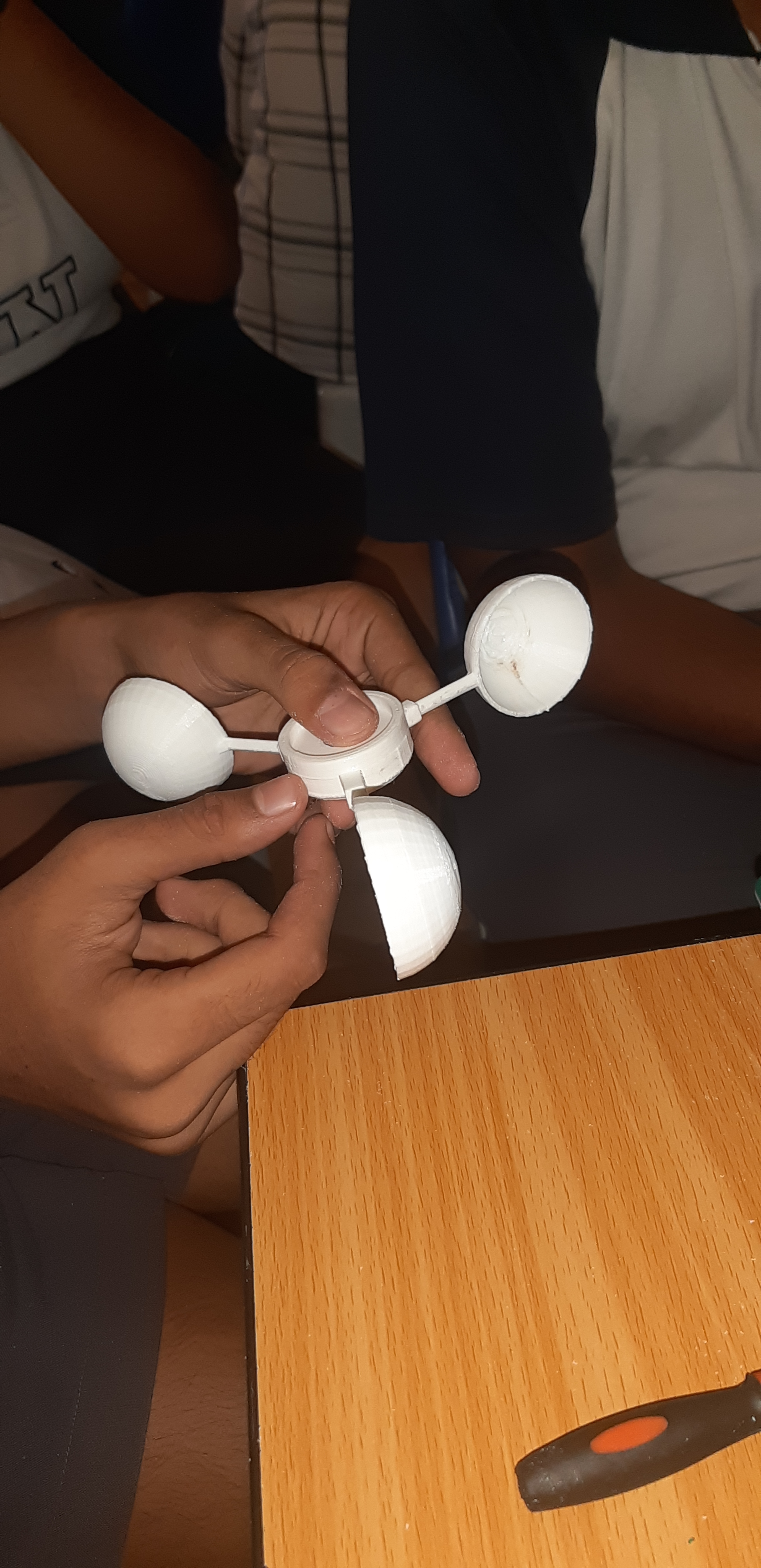
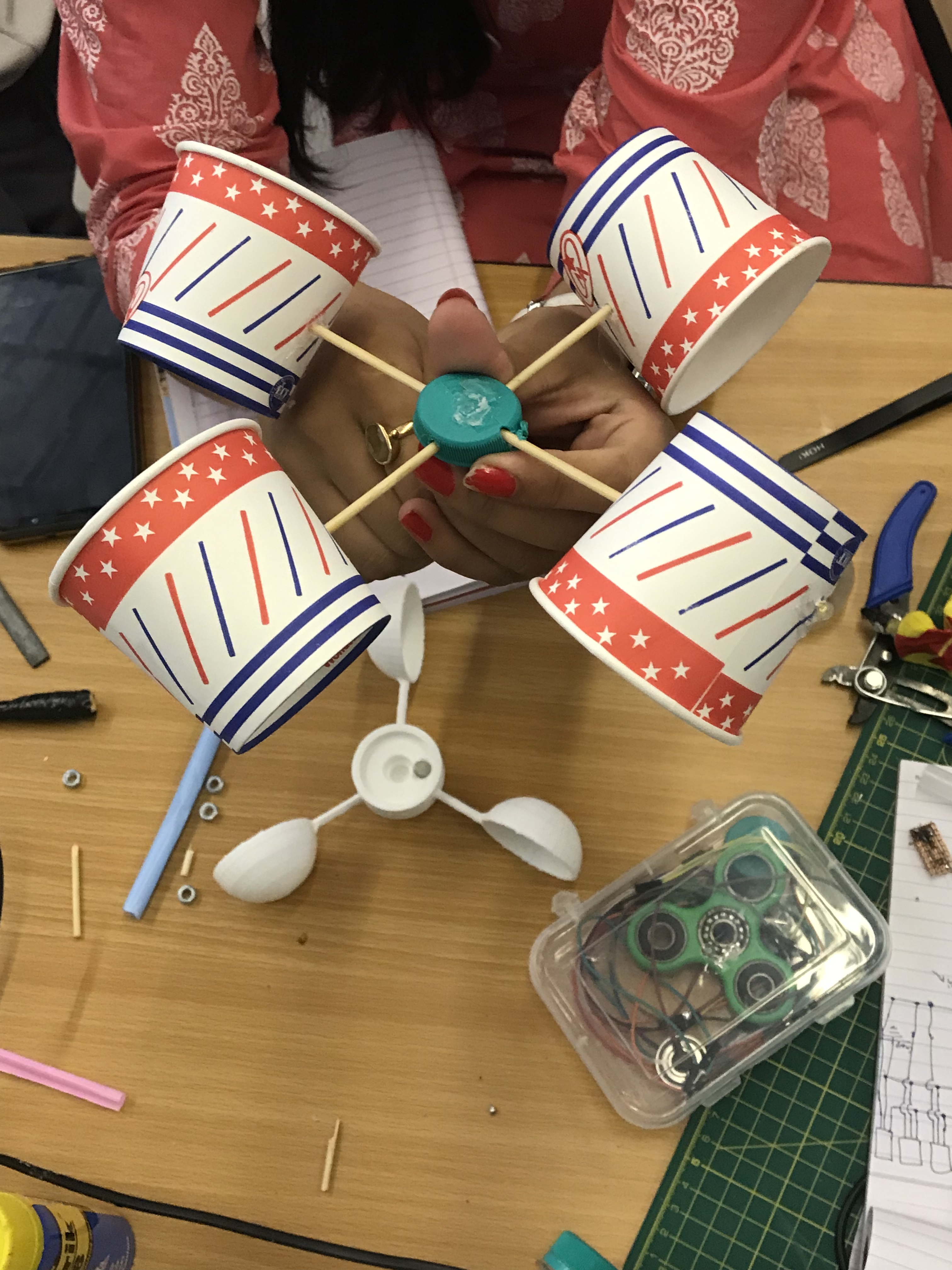
Finally first part done
@Ankita1 @Raghav @Tanmay @ananya13 @kavingaur123 @Devyansh
3 Likes
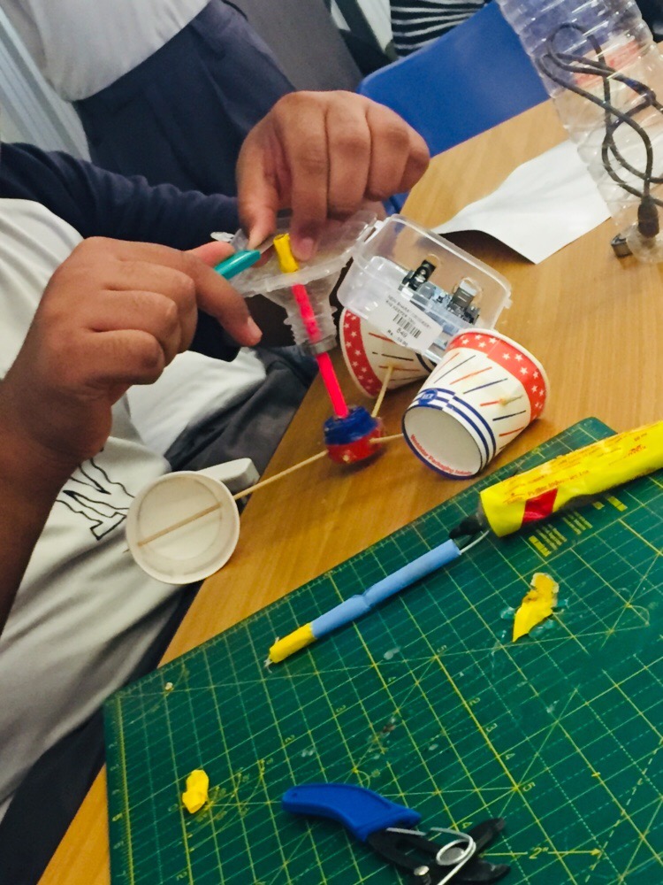
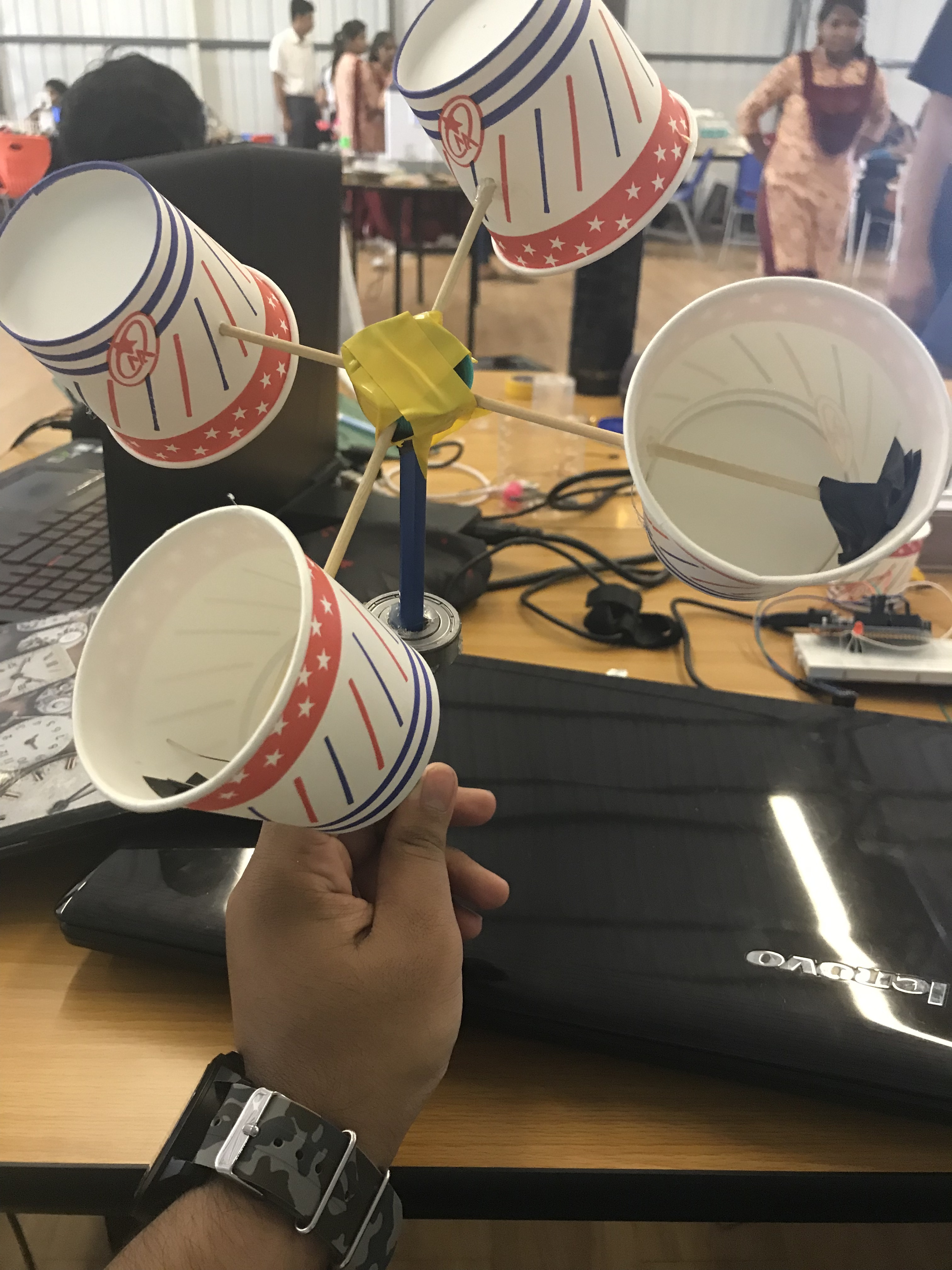
In order to join the parts in the process of making anomometer the students have first numbered all the wings of it so all later they should not face difficulty in the end while joing all the parts together https://stemgames.metastudio.org/uploads/default/original/2X/8/848cf184d464b4883151e903247a4e217bb609f6.mp4
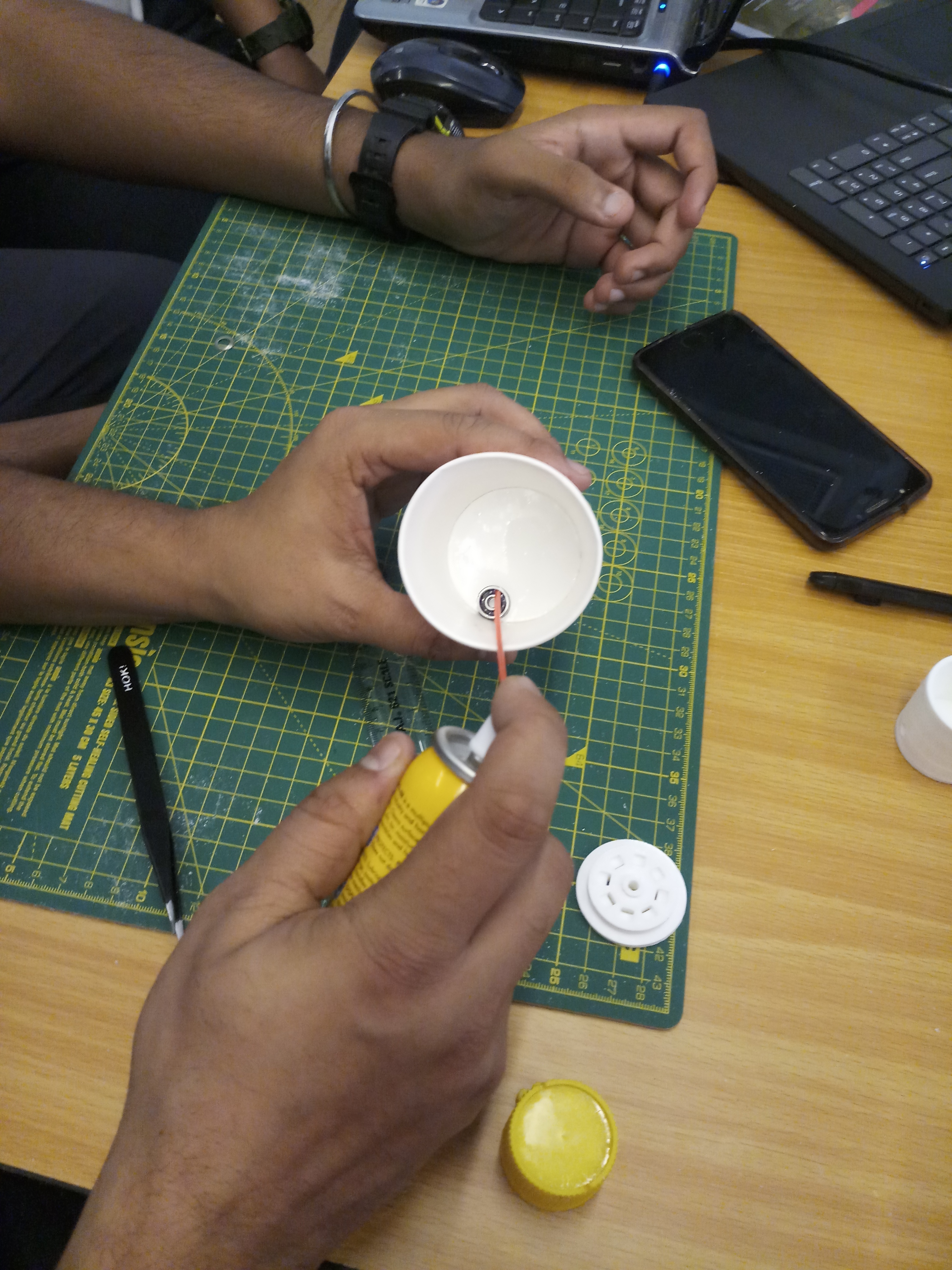
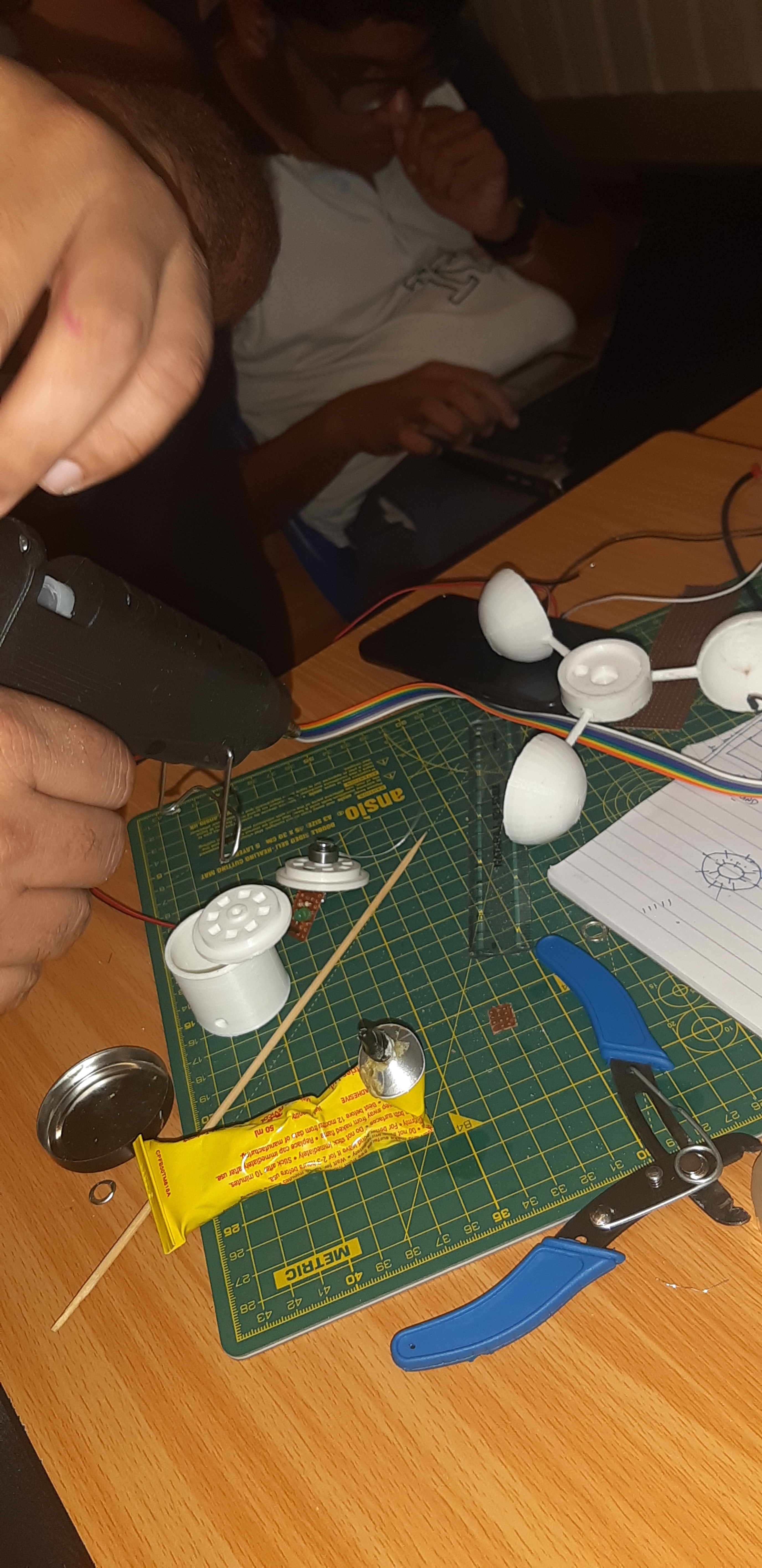
Step 3 for today is to remove extra grease from bearing to makmake it more smoother, for that the students are using zorrik chemical. They have first opened the bearing using twiser
and then put the bearing in the solution of zorrik…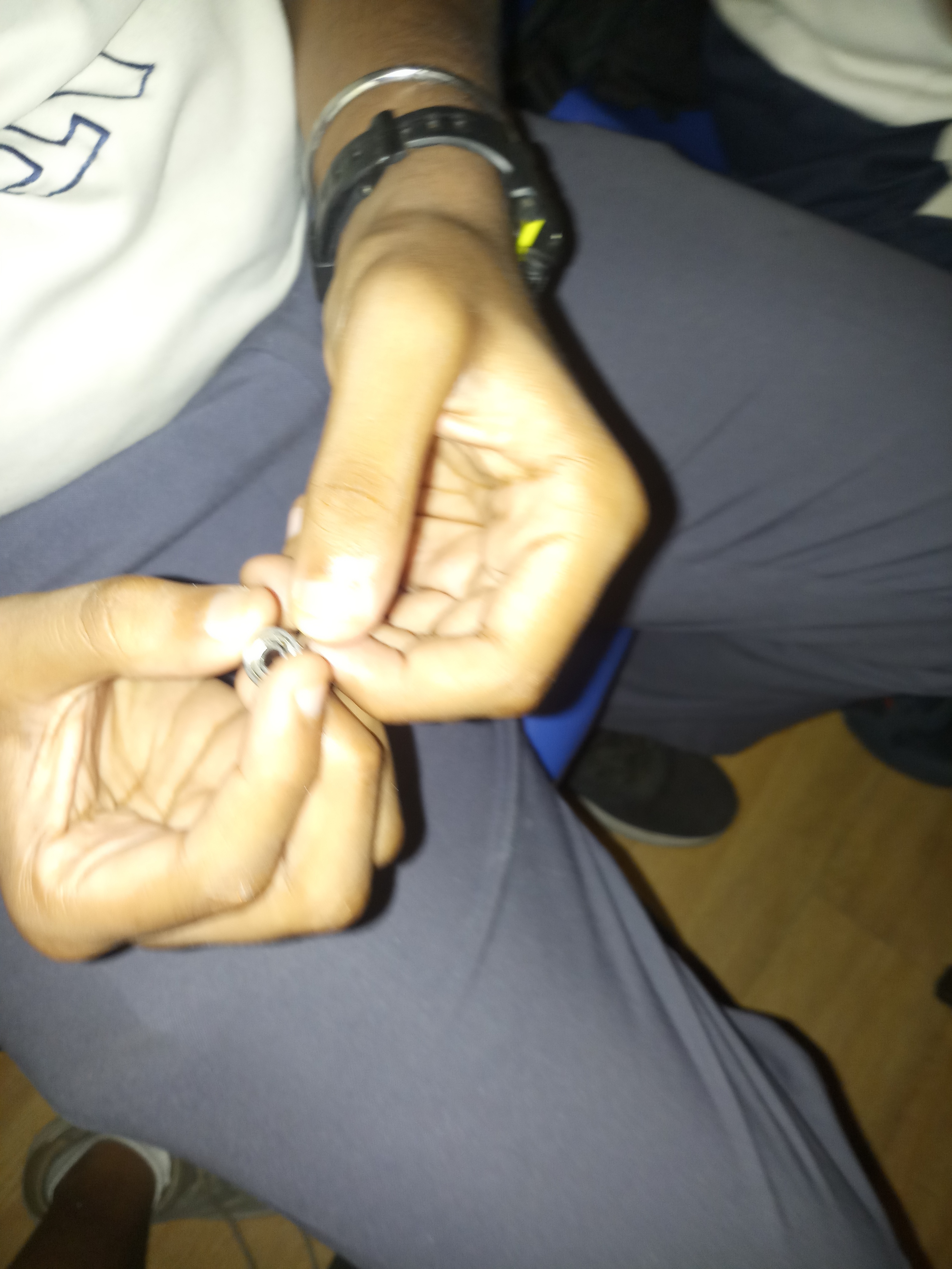
2 Likes
Hello there,
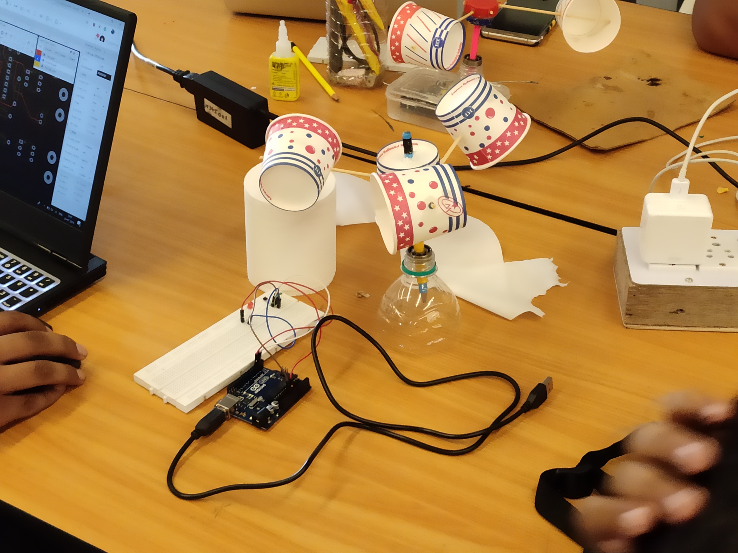
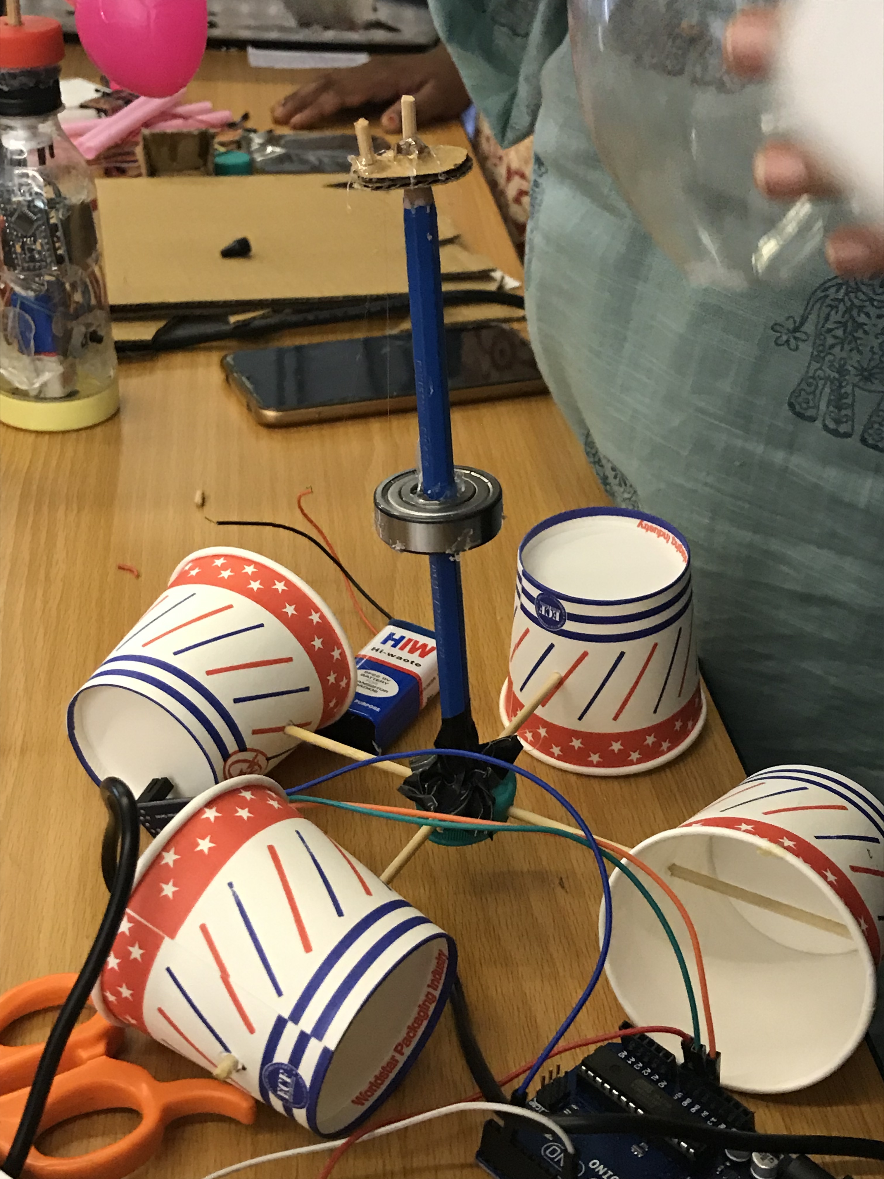
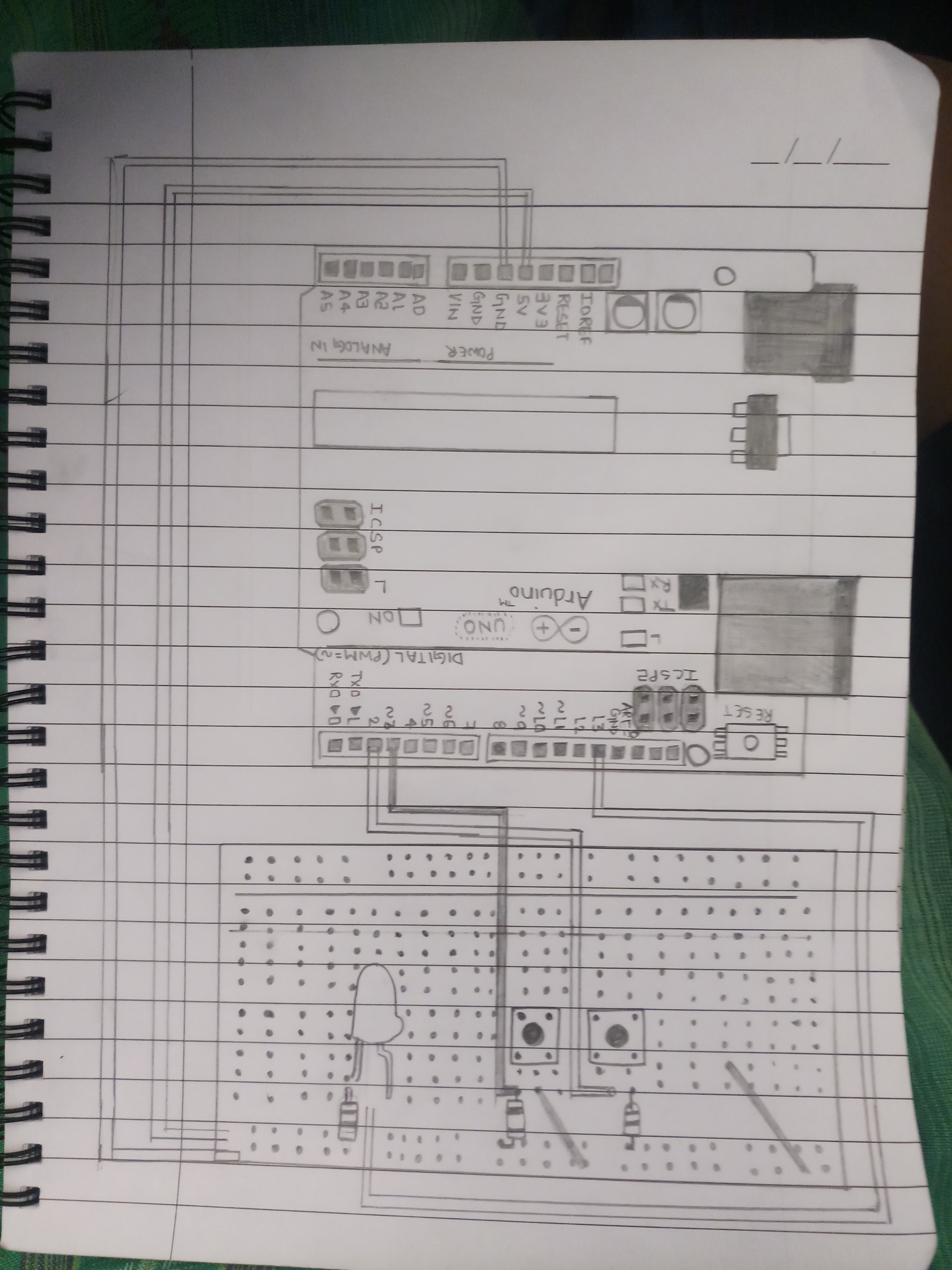
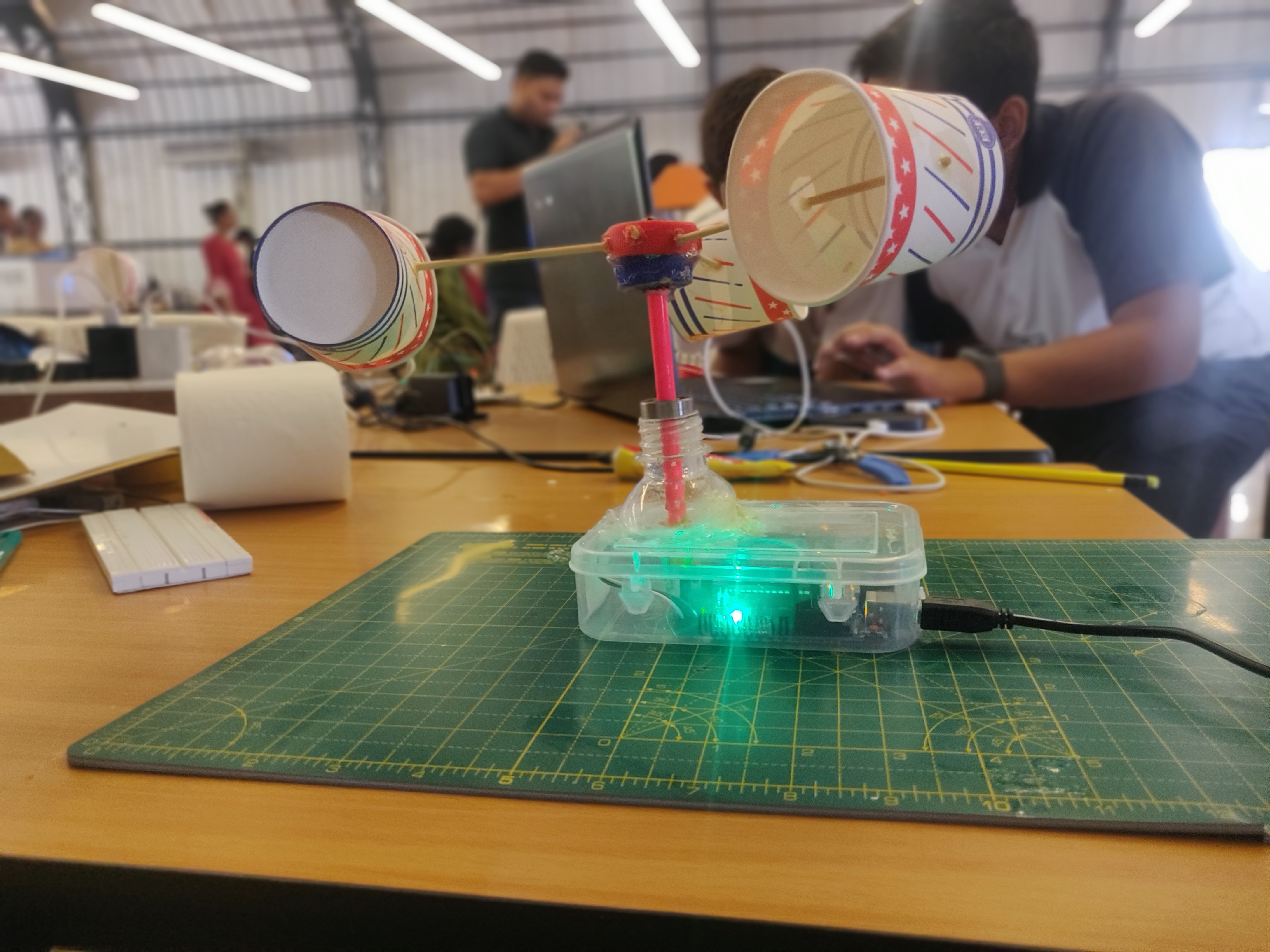
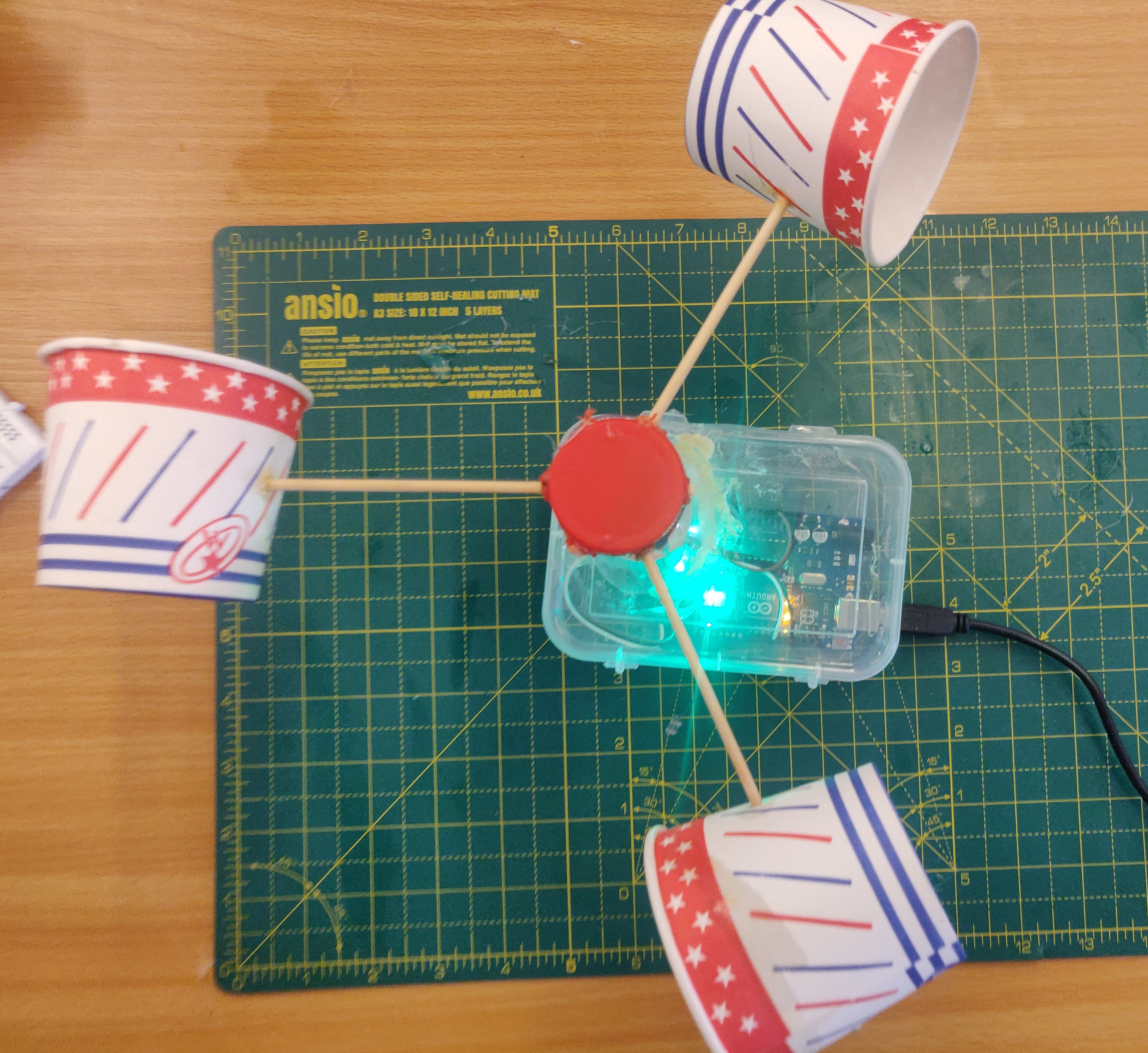
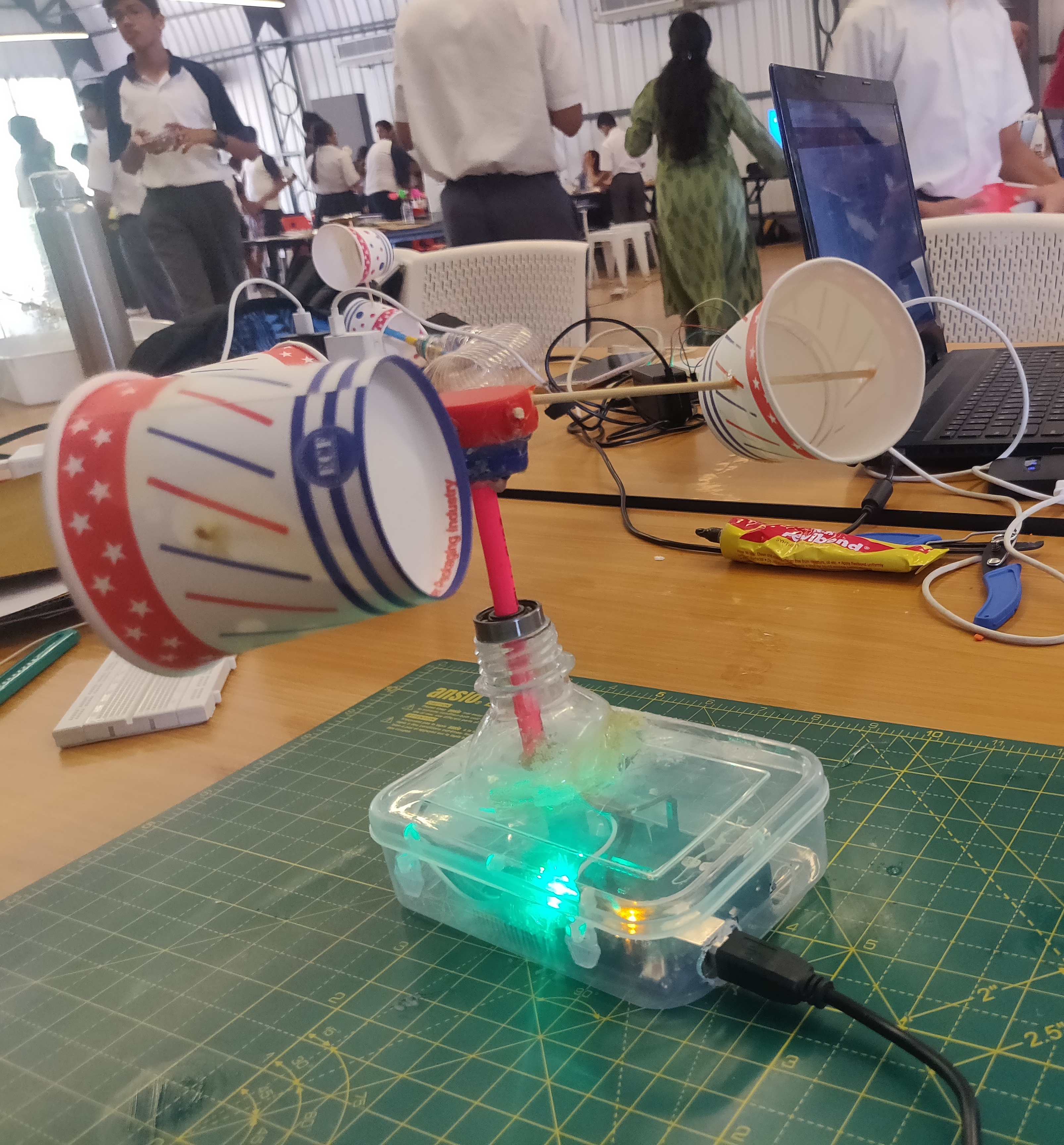
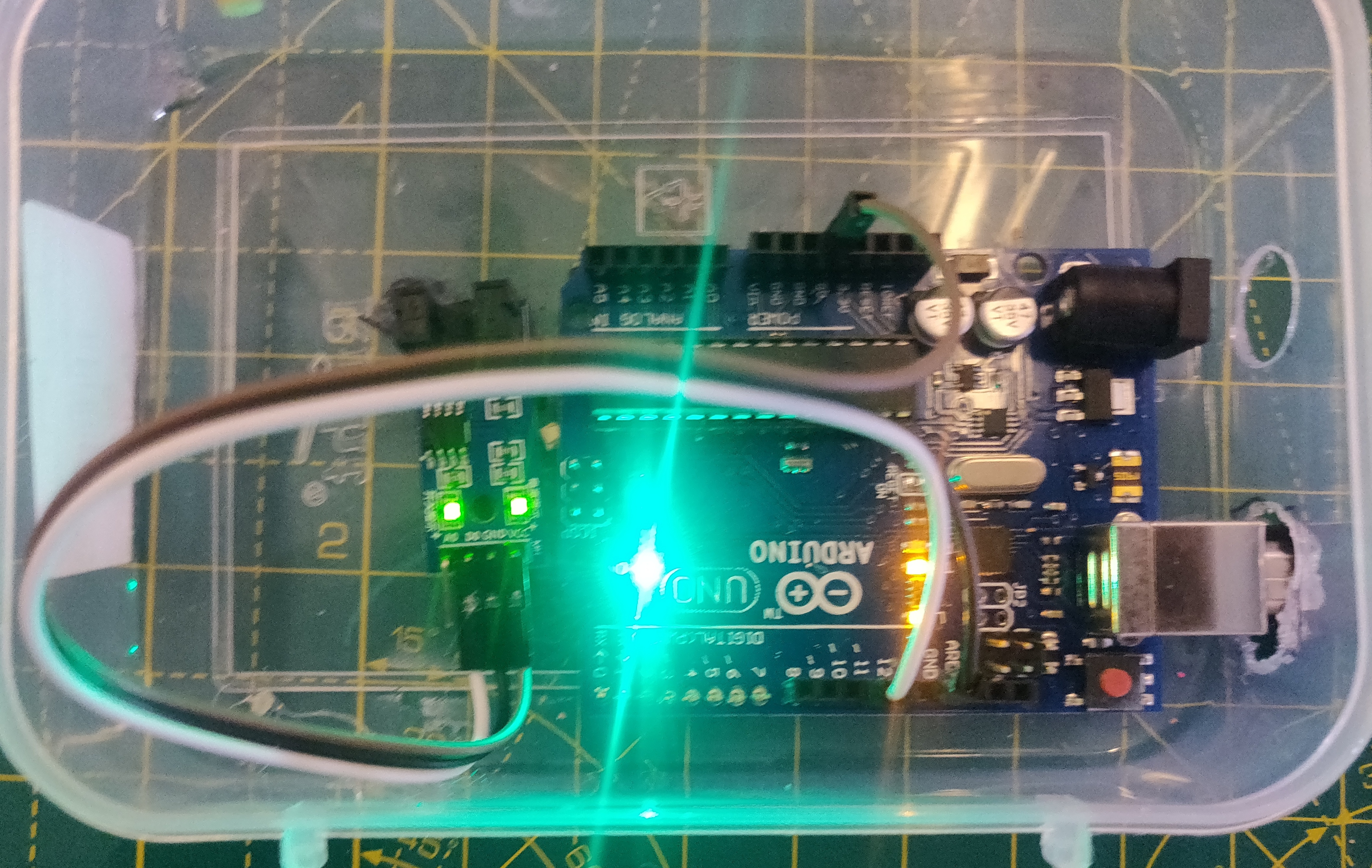
Finally, we completed our anemometer project in which we succeeded to get the number of rotation in a time interval.
where connections are as follows -:
IR sensor ----> arduino
VCC ----> VCC
GND ----> GND
DO ----> PIN 11
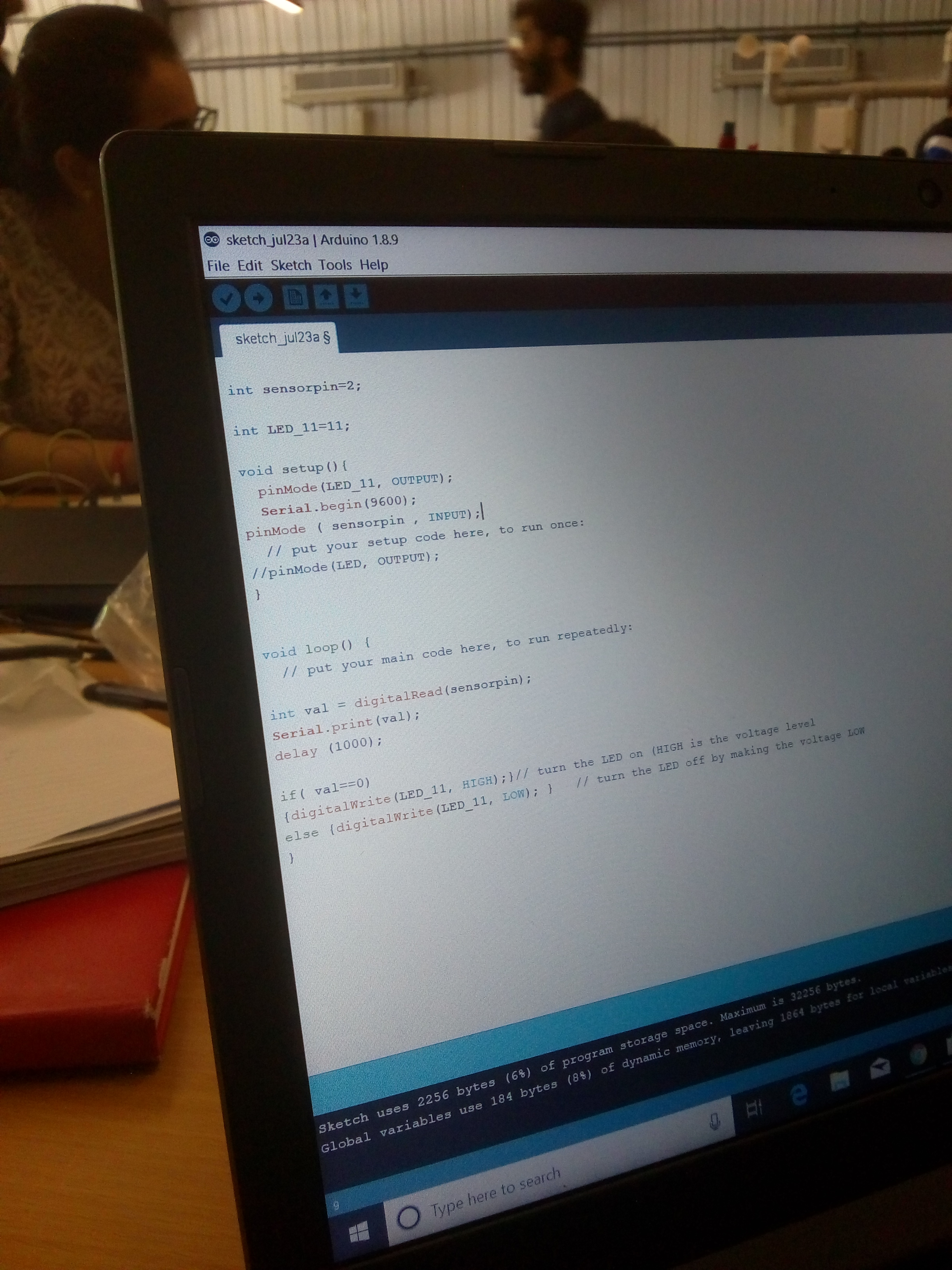
Arduino code -:
/*
- Here we initialize all the integers that we need for further processing and applying logic.
- flag is used to ensure that we get the precise pulses per rotation and no multiple pulses.
- pulses are the number of times obstacle passes through the ir grove.
- t1 is the time elapsed between the loop.
- t2 is the time in with we need the pulses.
*/
int flag =0;
int pulses = 0;
int t1 = 0;
int t2 = 3000;
int pulse_per_rotation = 2;
void setup() {
/*
- We define the pinmode as input because we need to get some data from the ir module to process and get the desired output.
- serial begin helps us to initialize the serial monitor to display the output on the screen.
*/
pinMode(11,INPUT);
Serial.begin(9600);
}
void loop() {
/*
- Here we check if we are getting input from the ir sensor and increase the pulse integer by 1 increment
- then we close the flag so that we don’t get multiple increments
*/
if(digitalRead(11) == 1 && flag ==0){
pulses ++;
flag = 1;
}
/*
*
- Here we compare the counter to get the pulses elapsed in time t2
- then we print the pulses by dividing it by number of pins to get the final output
- then we update the counter to get the latest values and make it ready for the next operation.
*/
if( millis() - t1 >= t2){
Serial.println(pulses / pulse_per_rotation);
pulses = 0;
t1 = millis();
}
/*
- Here we reset the flag to enable the program to accept the next input from the sensor
*/
if (digitalRead(11) == 0){
flag = 0;
}
}
2 Likes
2 Likes
1 Like