Creating a pedal vehicle

Multi pedal vehicles
This thread discussed the reasoning behind the choice of a multi pedal vehicle.

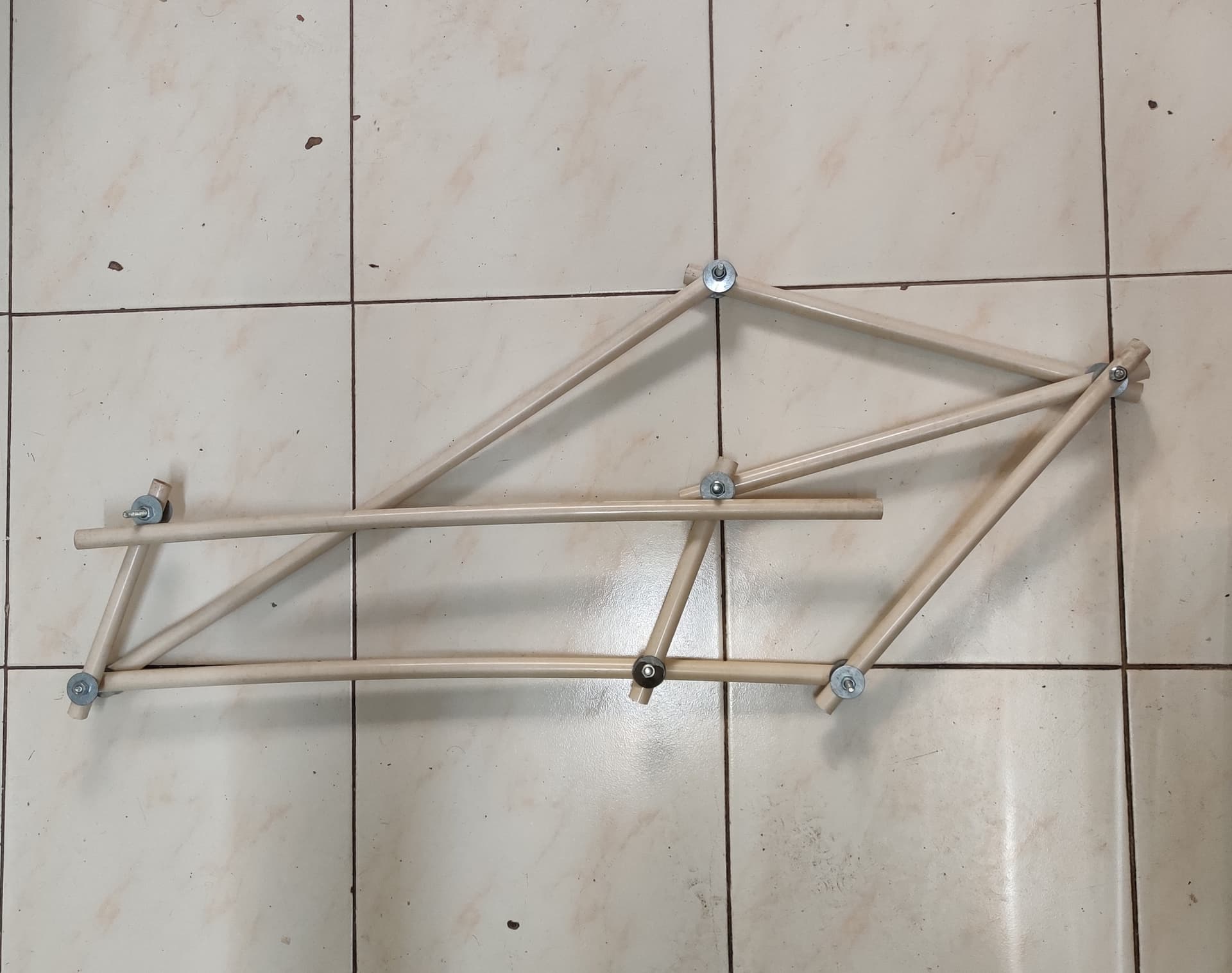
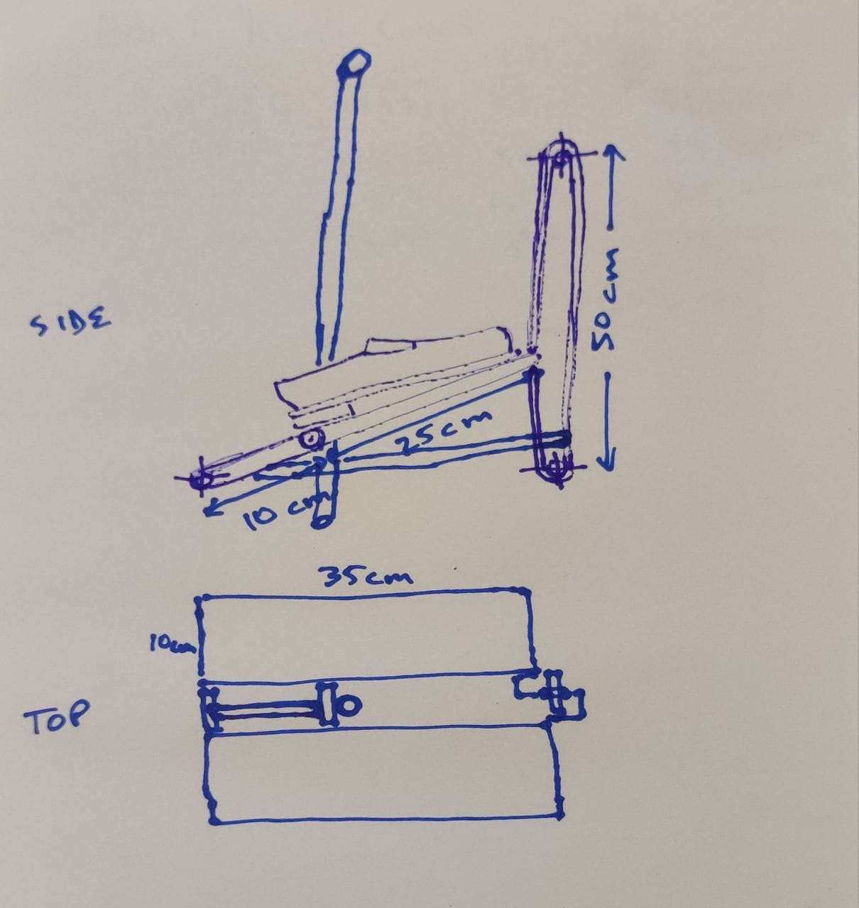
The following thread explores the construction of such a device.

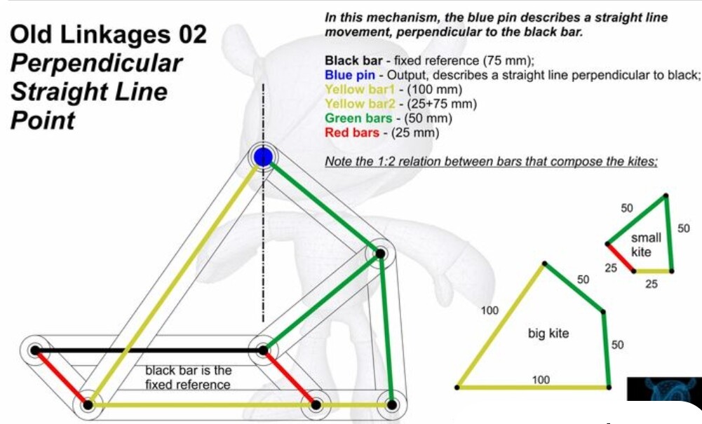
An important physical reality to be kept in mind is that the locus of a circle is the equal movement of two points oscillating along perpendicular axes, for fixed and equal distances.

Applied to pedal movement, this means that in order to emulate the motion of a wheel, two identical linear actuators need to be fixed perpendicular to each other, and to move in perfect tandem.

However, in the real world, once the choice of legs is made, there is no longer any reason to actually emulate a wheel, that is, to describe a full circle. Instead, an elongated oblong will do the needful, to provide a horizontal platform the ability to move level with a horizontal surface.

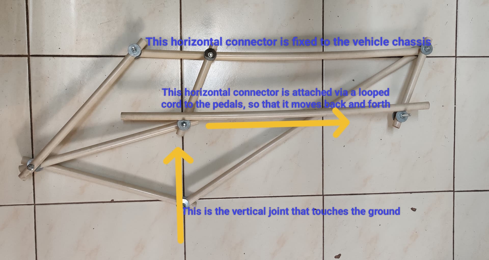
This means that the horizontal actuator needs to describe the full cycle, while the vertical actuator needs only to move the minimum distance that will ensure that the horizontal platform (the purpose for which this device is being described, and for which the prototype will be built) will not collide with the maximum unevenness of the ground over which the vehicle will move.

Modern sedan cars are designed for a chassis clearance of 17cm, while consumer off-road vehicles are designed for 20-25 cm. This is not a rule, but is certainly useful as a guide to designing a practical vehicle.

There is a second practical phenomenon that comes in useful for designing such a vehicle. This is the delivery of a comfort factor, for a passenger in such a vehicle. This comfort factor, the equivalent of the rolling movement of a wheel, is ensured by combining the action of 3 to 4 legs moving equal arcs that, in combination, add up to 360°. With 3 legs, the motion of each one is 120°, and with 4, each one is 90°.

In the earlier discussion, the minimum number of such assemblies needed to create useful vehicles is 4, in order not to have to take extraordinary care in locating the load that will be borne by the vehicle, whether it is just a single person, several persons, or one or more persons carrying baggage. Naturally, this is a minimum, as more such assemblies will continue to add stability and to decrease the energy load of each assembly, and the individual components of each assembly.

However, I’m suggesting here that the first prototype should have just 4 assemblies, to minimise the probable cost of the devices. To some extent, in fact, using many multiple assemblies will lower the cost of each one, but this will probably not happen to any productive extent, until the design is transformed into production of standardised units.

The next element of design for consideration is the prime mover.

5 Likes

Prime movers: there are two choices for creating a prototype vehicle, human and aided. Aided movers either supplement or supplant the energy that a human being can generate alone.

The simplest device is therefore a human powered vehicle, in which no external energy is used, so that there is no need to provide for external fuel and external energy conversion devices.

The simplest human energy convertors take the ability to move the hands and feet and convert these motions into the motions needed for the vehicle to move.

As described in the previous post, the motion needed is linear, but in two perpendicular directions. Which is actually really easy to do, with pivoted levers. If the pivots are made movable, the throw and energy exerted becomes variable, which is the equivalent of a geared drive to an axle.

Steering is also quite simple. It is only necessary to vary the relative speeds of the ‘inner’ and ‘outer’ sets of assemblies in order to turn the platform, which is also done by moving the pivots. Depending on where the driver’s seat is located, it may be necessary to vary the fore and aft speeds at the same time.

The simplest such vehicle will only have two sets of assemblies, but the rider will then have to balance in motion. Since there is little or no gyroscopic effect in the absence of wheels, it may have to be added. The advantage of adding a gyroscope is that it also acts as an energy storage device, like a capacitor, so that the driver/rider can rest while the vehicle is in motion. It may also help by providing some relief while ascending or descending slopes, in fact, this is quite likely. It might therefore be useful in the prototype, whether it is built with 2 or 4 assemblies.

As was earlier defined, the assemblies have been christened, in the course of our discussions at the Maker Labs, as rewheels, while the vehicle is called a chalopede. The variants described here are the multi pedal equivalents of the familiar cart and bicycle.

5 Likes

This is my attempt at drawing the basic mechanism of the vehicle, using helical springs wound on metal rods (pistons)

Each set of 4 piston assemblies represents one rewheel. They are offset from each other by 90°, so one is fully extended, in contact with the ground, and one fully retracted, the other two in between. The other 3 rewheels are in the same state. At any given time, with this arrangement, 4 pistons will always be in contact with the ground.

As can be seen in the drawing, the individual pistons are also offset horizontally, also 90° from each other in sequence. Thus, the piston in contact with the ground is shown at one end of the horizontal slot in the platform (chassis), and is about to be retracted and returned to the other end of its slot. The other 3 are in varying positions, again, offset in a sequence of 90° of separation from each other.

To achieve this is, as remarked in an earlier post, fairly easy, using foot or hand pedals. In addition, the mechanism should drive a wheel, fairly heavy and, if only two rewheels are used instead of 4, of reasonably large diameter, to act as a gyroscopic stabiliser and, dual purpose, a flywheel/capacitor. If 4 rewheels are used, only a small heavy wheel will be necessary, to act as a flywheel/capacitor.

3 Likes

Since, in this simplified arrangement, 4 pistons are in contact with the ground, the load bearing capacity of each spring needs to be about 25kg, in order to handle a total loaded weight of 100 kg in this first prototype. If the rider is taller and heavier, the spring capacity may need to be around 30kg.

This spring calculator informs that such springs can be made of standard spring metal, ASTM 227, with around 30 coils of 9 gauge, to handle a throw of 25 cm. This is not precise, and there is a simple reason, that the prototype is intended to be built from recycled shock absorber parts acquired in the local spare/scrap market in Kurla. This has not yet been explored in detail, but obviously, using some scrapped shock from the market saves the trouble and expense of engineering a theoretically ideal device. Standard shocks also have handy readymade casings that should make it easier to fix the other parts of the drive mechanism.

5 Likes

Having said which, in an arrangement that draws the spring upwards with human power, and releases it down to touch the ground using the energy stored in the helical coil, there is no particular reason to have only one piston in each set of four as the active one. It should be fairly simple to rig the levers to keep 2 or even 3 in constant contact with the ground.

Just thinking aloud, this reduces the strength needed to compress the unused springs to a third, while tripling the load bearing capacity of the rewheel in motion.

That means each shocker need have an effective load capacity from 8 to 10kg only, making them far lighter.

And, hopefully, cheaper.

And, another bonus, the ride will surely be even smoother.

3 Likes

This animated clip describes graphically how a full circle is created from pairs of perpendicularly moving points. In a real world pedal vehicle, of course, one saves an enormous amount of energy by limiting the locus to a reasonably flattened oval.

4 Likes

This thread has, so far, described the principle behind a novel approach to mechanised transport. Instead of the traditional wheel, it proposes the use of psuedo-legs, whose combined movement adopts the essential geometrical principles of the rolling wheel.

However, being legs, a real practical vehicle will probably not need an ultra smoothened path in order to deliver a comfortable ride. This has important consequences for the design and implementation of road interconnections between human habitations and workplaces, mainly, vast cost savings.

At the same time, the design points towards optimisation of the absorption of shocks encountered while traversing an uneven path. In wheeled vehicles, this is almost always a completely separate mechanism, both costly and unwieldy to implement. This could possibly be mitigated or overcome by the use of multiple legs, which sequentially take up the partial load, thus perhaps doing away entirely with a dedicated suspension machine.

Taken together, it appears that the overall cost of adopting such an approach might be a saving, in comparison to wheeled vehicles and hard smooth roads.

There is also an ecological implication to the elimination of hard smooth roads, which are in effect gigantic, continental sized, artificial rock formations. Nobody has, and possibly it cannot be done now, researched the actual ecological impact of such terraforming.

So here we are now. What does it take to step forward from ideating to tinkering?

1 Like

@punkish forwarded a video of a tinkering project to build a Janssen-legged semi-pedal bicycle. This one:

Comments:

  1. This is a straight implementation of the Jansen leg design (Theo Jansen, the Dutch artist, creator of the Strandbeest series of walking automatons).

  2. The video is delightful. The builder works in an extremely organized fashion, using jigs and fixtures and all the right precautions to build a fairly complex model with the right accuracy.

  3. Having said which, he has replaced a bicycle wheel whose structure is elegantly created from really lightweight bicycle spokes, with four large and heavy looking legs made out of SS pipe. It isn’t at all clear why the legs are so evidently overdesigned. It might well be that a similar structure/mechanism could have been built to do the job just as well, also made from bicycle spokes.

  4. It isn’t clear either why he went to so much trouble to build the complicated rear drive wheel, and then stopped, without replacing the simpler front wheel. Had he done so, he might well have further ideated a l-to-r differential for the 4 front legs, thus making it possible to turn the cycle from side to side in motion, without having to rotate the whole forward mechanism.

  5. As has been discussed in previous posts, the use of 4 legs makes for an absolute wheel like smooth contact with the ground. It is, however, possible, and this needs to be built and tested, that 3 legs will also work as effectively.

  6. If the side to side differential drive is built into both the fore and aft pedal mechanisms, turning the bicycle will be much more agile than with a traditional 2-wheeled bicycle design.

Other thoughts, such as replacing the Jansen design completely, with a springy material instead of rigid steel pipe, will not only be much simpler to fabricate, but will also be far lighter. It may compete in weight with the orginal bicycle, which is an important consideration for a practical replacement to an HPV whose design has been developed and nurtured for just over 200 years (the German draisine was introduced in 1817). Perhaps either single or a small bunch of spokes can be used instead of the pipe, thus retaining much of the Jansen design approach, and adding both strength with inbuilt springiness.

Or, as in the discussion prior to this post, dump the Jansen structure and just use simple helical springs as linear motors.

4 Likes

After some more thought, I’m coming around to the realisation that, while each leg needs a combination of vertical and horizontal motion, it isn’t necessary at all that both these motions need independent drive trains.

I think that it ought to be possible to construct a chassis (a horizontal rigid structure) that supports helical spring elements laid horizontally. Using levers, each spring can be used to drive a pair of linear elements, one vertically and the other horizontally. The ratio between these two motions determines how much energy is used to support the platform vertically, and how much to move it horizontally.

Similarly, the amount of throw of each element helps determine the velocity of movement horizontally. Vertically, it helps sustain ground clearance, which is important because one of the fundamental features of a multi-element drive is that relatively smooth ground is not an imperative. In fact, even relatively hard ground is not an imperative, as the use of multiple elements will tend to minimise slip.

The other features of such a drive, turning and reversing, remain the same. They are relatively trivial to engineer, using sets of levers that adjust the pivot points placed between the actual helical springs and the linear elements.

In the driver’s seat, power can be obtained by pedaling with the legs, or using an external power source such as an electric motor (that may itself be a linear motor, but in my experience these are ridiculously expensive because nobody has ever created a heavy duty ubiquitous use case). Steering needs little or no power, as it merely moves the pivot points that determine the relative motion of the legs on either side of the platform. Also the fore and aft legs, because 1. that ensures comfort (and therefore safety) of the passenger during a relatively higher speed and sharper turn, and 2. eliminates slip between the fore and aft of the vehicle, which reduces wear and tear on the end of the leg in contact with the ground.

This design change ought to significantly reduce both the cost and the weight of the vehicle.

Reducing the number of energy transforming elements also means that more expensive elements, such as precision linear electric motors, might become more affordable for a motorised vehicle. In turn, this opens the door to designing a digital controller to both steer and to move the vehicle over rougher terrain and up/down slopes.

3 Likes

Why not use rotary motors with appropriate linear drive conversion? At least initially.

3 Likes

It’s a possibility.

However, a motor with linear convertor will be a very rigid system. There is no way, without a sophisticated feedback system built into the motor controller, for the vertical leg to travel just the distance needed to the ground.

A motorised system with a controller is a precision combination of drive and suspension. It is probably a very fine way to build an integrated mobility platform for random terrain.

My thinking, for choosing to begin with a simple mechanism with no electronics or digital elements, is to prove the working of the basic concept, of a pedal vehicle built from a combination of two linear elements placed perpendicular to each other, at the least possible cost for the prototype.

With the elements being powered by the stored energy of a helical spring, suspension is accommodated, in a rough and ready manner, by the spring itself. It may not be a precise solution, but the lack may be compensated by the large number of legs. That’s something that needs to be tested with a prototype.

In a working model, such unevenness, caused by travel over rough terrain, may build up thanks to sympathetic vibrations, and cause the passenger discomfort. However, it is possible that the unequality between the energy of the distributed impacts of many legs traveling different distances, thanks to the uneven terrain, will compensate. When all legs travel the same distance over smooth terrain, there won’t be any unexpected impacts in the first place, and the energy of impact ought to be absorbed by the mechanical properties of the spring.

4 Likes

A post on the related project for building leg motions links to the files with drawings of the necessary linear motion mechanisms.

1 Like

The three dimensional model in the video attached to this tweet shows very clearly how balls moving in a straight line simply describe the movement of a wheel.

From here, it is a short jump to eliminating the wheel itself, and using multiple legs instead of a wheel. It is empirically demonstrated already, that a workable approximation needs only three legs, with additional smoothness of motion equivalent to a rubber-tyred wheel achieved by using four.

That takes care of the part of the vehicle in contact with the ground. In Switzerland, a development group has been working on a different stage of the vehicle, with the intention of creating a mechanism that can, almost intuitively, handle complex surfaces like steps. In this model, hinged legs have wheeled feet, resulting in a very capable hybrid motion. Its capabilities are shown in this video.

Emulating this hinged leg (which is hinged at the ‘knee’ is not very difficult for the section of a load carrying platform, the intent of which is to deliver a level motion at the platform for the widest possible range of contours of ground surface, up to the point where the gradient exceeds the degrees of freedom available at the knee.

This is the simplest and oldest linkage mechanism that I have found described in a document available online.

It removes all the nuisance of having to identify carefully engineered manufactured items such as precision linear motors and well made helical springs. It can be put together in a simple workshop, using either lightweight wood or bamboo, or light metal pieces.

The power train for the drive mechanism can be, as in a ‘traditional’ bicycle, foot pedals. The throw of the pedal can be adjusted using hand operated levers, enabling control of speed and direction.

Direction is controlled, as described in earlier posts, by differential speed control of the left and right side legs. With very slight additional complexity, it is possible to add slip control, by introducing variable speed control fore and aft as well. Although feet are, by their basic nature, far more hardy than rubber wheels, the life of the mechanism would be extended much longer with positive slip control.

When the basic foot pedal mechanism is replaced with any powered system, the vehicle becomes the equivalent of a modern motorcycle or car.

In one of the earlier discussions either here, or in either of the linked design discussions, I may have mentioned that it seemed to be a good idea to follow the industry norm for comfortable motor vehicles, to keep a road clearance of 17cm.

Now, I don’t know why this number, what the imperative could be, but assuming that decades of development of motor vehicles by large manufacturers got it right, where does this translate, in terms of a simple road ready HPV?

I am hoping to build one myself, sooner rather than later, and the first thing is to plan a basic parts list.

The assembly of each vertical foot needs 9 lengths of rods, 2 each of unit length 1, 4 & 5, and 3 of unit length 2. Some scribbling on paper shows that a clearance of 17cm translates comfortably to a basic unit length of 25cm, very easy to work with.

I am hoping to get to a bamboo shop not too far away, where I can pick up the rods the assembly needs. With 4 discrete foot units, each corresponding to the wheel of a cart, a total of 144 rods are needed. If bamboo rods are not possible, perhaps lightweight wooden rods can be sourced, and if not, for this prototype, lightweight aluminium piping is freely available in most hardware markets.

Length
Again, with some more scribbling on paper, it turns out that placing the fore and aft feet such that they just about touch each other at full extension needs a chassis that is no more than 300cm long. But this is three meters, much too long for a simple HPV, is my instant impression.

Two things are possible: firstly, to synchronise the movement of fore and aft feet so that they don’t touch. Second, to offset the fore and aft feet so they can’t touch. This is far easier to do, actually.

The chassis itself must have longitudinal rods running from the front all the way to the back, and it is a simple fix to put the fore feet on the outer side of each one, with the aft feet on the inner side. Now they can’t touch at all, and the only consideration is how far apart one ought to keep them.

In a full size bicycle, the hubs are usually about 90cm apart, and so 90-100 cm is probably good enough for getting started with a prototype. Each foot is about 150cm at full extension, and the vertical member is exactly at the 100cm point.

Since there are four feet on each leg, (with two legs each fore and aft), the chassis needs 8 longitudinal members, the same length as the frame. Since the ‘hubs’ need to be about 100cm apart, the frame needs to be a minimum of a further 100cm (50cm each for the fore and aft legs) long. This leads to a specification of a 200cm long vehicle.

Breadth
This is actually a function of the diameter of the rods/pipes that are available for this prototype. Very simply, it is 18x of that diameter, being 2x8 dia for each leg, and another 2dia for the frame. During assembly, the amount of clearance necessary for tangle-free operation might need adjusting, of course.

Height
The lowest clearance is, by design, 17cm, but this is free space, with no frame assembly at all.

The space needed for vertical movement of the individual feet is contained, actually, within the largest possible movement in a vertical direction, of the foot assembly, which is 25cm. All other mechanisms therefore need to be contained in the space available above this rectangular box, of size 25x200x(18x[rod dia])cm.

The mechanisms needed are, in short order, a seat with a pedaling mechanism to drive the feet and the legs, and the speed control/steering mechanism. The latter is in fact a fairly simple linkage, or rather two mechanisms, to adjust the throw of the horizontal movement of the feet, and may possibly be accommodated in the same vertical space as the seating.

More scribbling is needed, in order to define the upper limits of these mechanisms, and the space they need to occupy.

2 Likes