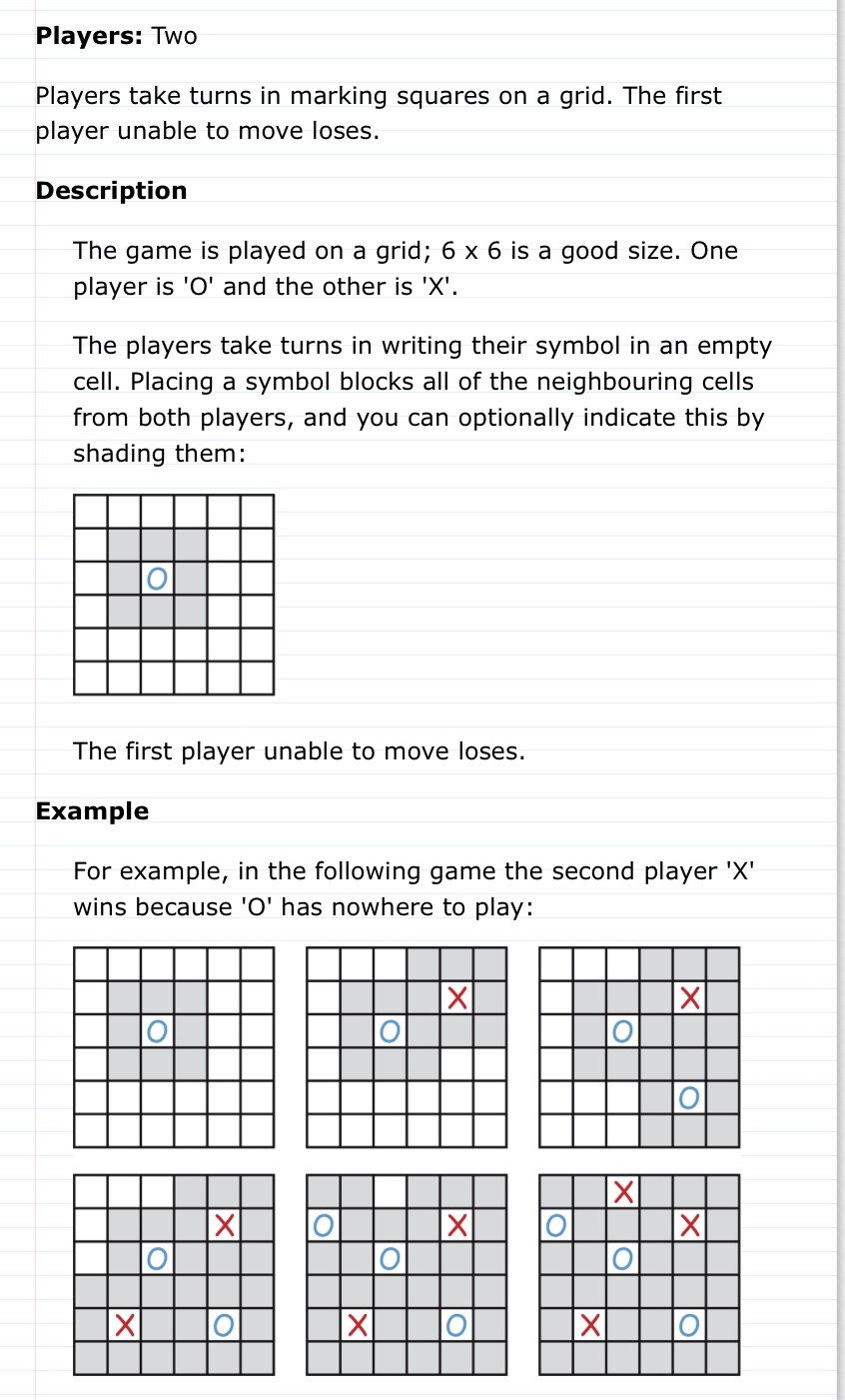
FILL THE BOARD GAME WITH CONSOLE
Game:
Code (with keyboad):
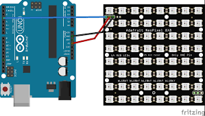
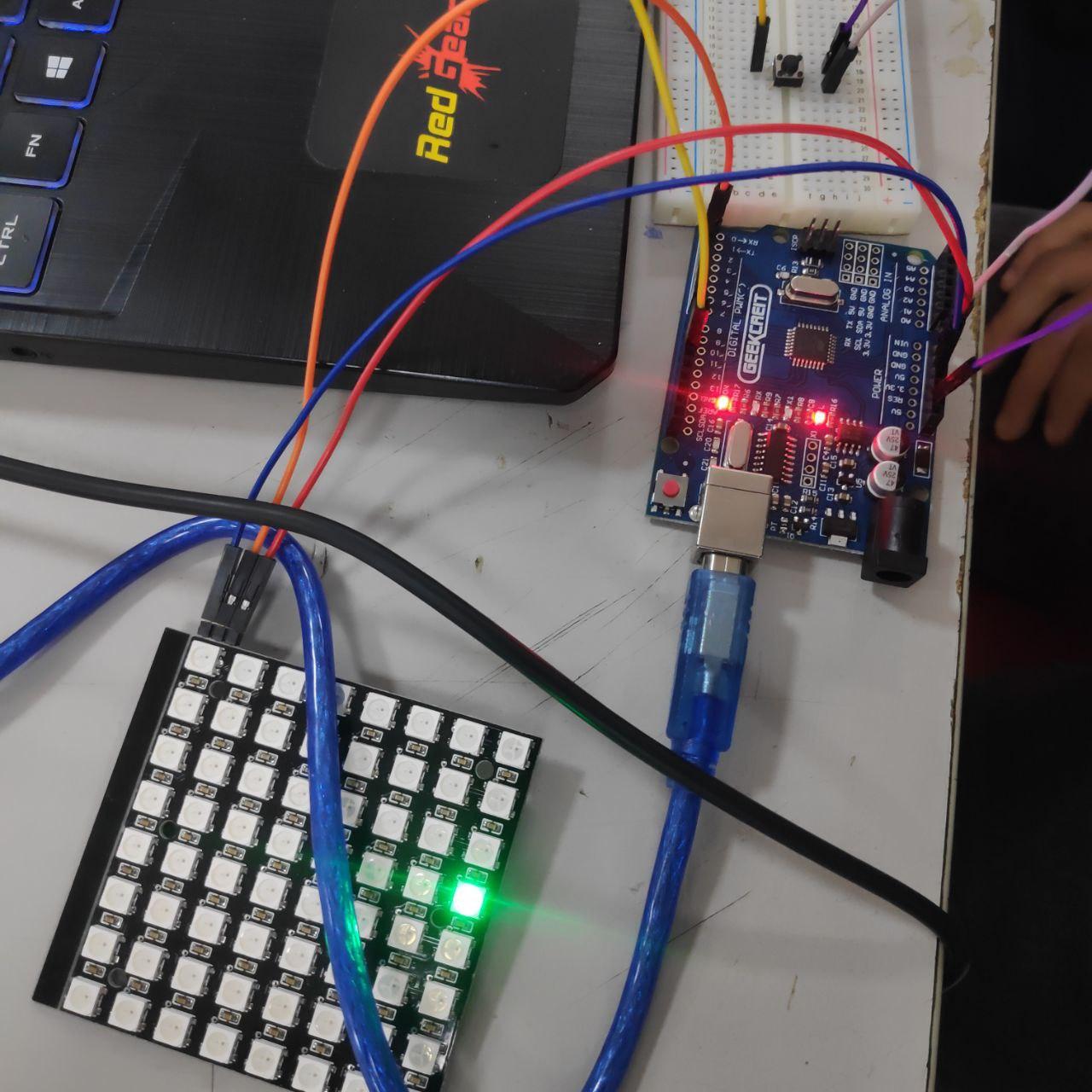
#include <Adafruit_NeoPixel.h>
#ifdef __AVR__
#include <avr/power.h>
#endif

int pin         =  2;
int numPixels   = 64;
int pixelFormat = NEO_GRB + NEO_KHZ800;
int x;
int x2;
int g[64] = {};
int b[64] = {};
int y[250] = {};
int k = 0;
int j = 0 ;
int l = 0;
int i;
int m = 0;
int n =0;
int h;
int o =0;

Adafruit_NeoPixel *pixels;

void setup() {
#if defined(__AVR_ATtiny85__) && (F_CPU == 16000000)
  clock_prescale_set(clock_div_1);
#endif
  pixels = new Adafruit_NeoPixel(numPixels, pin, pixelFormat);
  pixels->begin();
  pixels->clear();
  pixels->setBrightness(2);
  Serial.begin(9600);
  x = 0;
  x2 = -1;
  int green = pixels->Color(0,255,0);
  int red  = pixels->Color(255,0,0);
  int blue = pixels->Color(0,0,255);
  int no = pixels->Color(0,0,0);

}


void loop() {
  char s;
  s = Serial.read();
pixels->setPixelColor(x, pixels->Color(0,255,0));
for(n=0;n<250;n++) {
    pixels->setPixelColor(y[n], pixels->Color(198,198,198));
}
for(k=0;k<64;k++) {
    pixels->setPixelColor(b[k], pixels->Color(102,0,102));
  }
for(i=0;i<64;i++) {
    pixels->setPixelColor(g[i], pixels->Color(255,0,0));
  }


pixels->setPixelColor(0,pixels->Color(198,198,198));

if(s == 'd'){
  pixels->setPixelColor(x,(0,0,0));
  if((x+1)%8 == 0){
    x = x-7;
  }
  else{
      x =x+1 ;
  } }
if(s == 'a'){
  pixels->setPixelColor(x,(0,0,0));
  if((x)%8 == 0){
    x = x +7;
  }
  else{
      x = x-1;
  }}
if(s == 's'){ pixels->setPixelColor(x,(0,0,0));

      x = (x+8)%64;
  }
if(s == 'w'){pixels->setPixelColor(x,(0,0,0));

  if ((x%64)>7){
      x = (x-8)%64;}
  else{
    x = (56+x)%64;
  }
   }

if(s == 'g'){
  if (o%2 == 0){
    g[j] = x;
    j = j+1;
    o = o+1;
  }
  else if(o%2 == 1){
    b[l] = x;
    l = l+1;
    o = o+1;
  }
  if((x+1) % 8 == 0){
    y[m]=x-1;
    y[m+1] = x+7;
    y[m+2] = x+8;
    y[m+4] = x-9;
    y[m+3] = x-8;
    m = m+5;
  }
  else if ((x)%8 == 0){
    y[m+1] = x+1;
    y[m+2] = x+8;
    y[m] = x+9;
    y[m+4] = x-7;
    y[m+3] = x-8;
    m = m+5;
  }
  else{
  y[m]=x-1;
  y[m+1] = x+1;
  y[m+2] = x+8;
  y[m+3] = x-8;
  y[m+4] = x+7;
  y[m+5] = x+9;
  y[m+6] = x-7;
  y[m+7] = x-9;
  m = m+8;
  }
}
pixels->show();
}
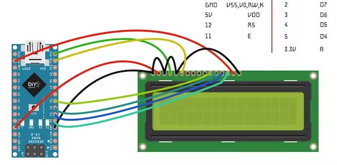
Code (with console):
#include <Adafruit_NeoPixel.h>
#ifdef __AVR__
#include <avr/power.h>
#endif
#include <LiquidCrystal.h>
const int rs = 12, en = 11, d4 = 5, d5 = 4, d6 = 3, d7 = 2;
LiquidCrystal lcd(rs, en, d4, d5, d6, d7);
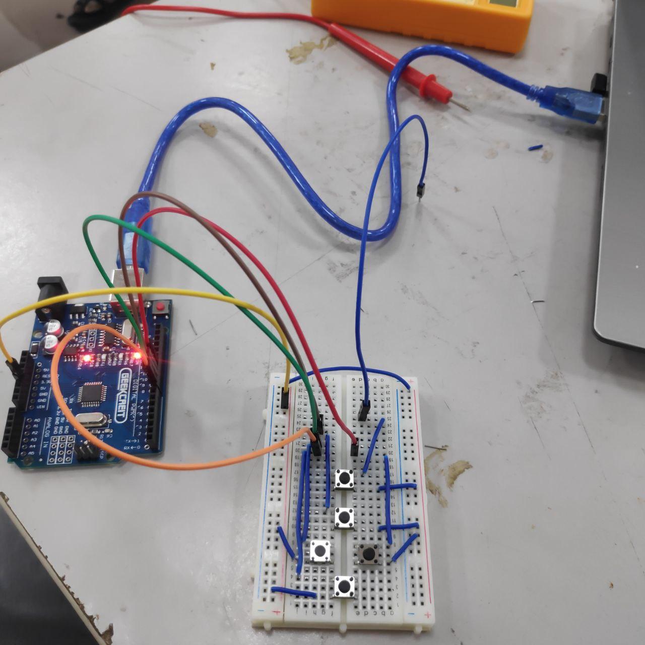
int enter = 6, right = 7, left = 10, up = 8, down=9;
int enterstate = 1, rightstate = 0, leftstate = 0, upstate = 0, downstate=0;
int pin = 13;
int numPixels = 64;
int pixelFormat = NEO_GRB + NEO_KHZ800;
int x;
int g[64] = {};
int b[64] = {};
int y[250] = {};
int k = 0, j = 0, l = 0, i = 0, m = 0, n =0, o = 0, h = 0;
Adafruit_NeoPixel *pixels;
void setup() {
#if defined(__AVR_ATtiny85__) && (F_CPU == 16000000)
clock_prescale_set(clock_div_1);
#endif
pixels = new Adafruit_NeoPixel(numPixels, pin, pixelFormat);
pixels->begin();
pixels->clear();
pixels->setBrightness(2);
Serial.begin(9600);
x = 0;
lcd.begin(16, 2);
lcd.setCursor(0,0);
lcd.print("Press Enter");
lcd.setCursor(0,1);
lcd.print("to Start");
delay(1000);
pinMode(enter, INPUT);
pinMode(right, INPUT);
pinMode(left, INPUT);
pinMode(up, INPUT);
pinMode(down , INPUT);
digitalWrite(enter,HIGH);
digitalWrite(right,HIGH);
digitalWrite(left,HIGH);
digitalWrite(up,HIGH);
digitalWrite(down,HIGH);
}
void loop() {
rightstate = digitalRead(right);
leftstate = digitalRead(left);
upstate = digitalRead(up);
downstate = digitalRead(down);
enterstate = digitalRead(enter);
char s;
s = Serial.read();
for(n=0;n<250;n++) {
pixels->setPixelColor(y[n], pixels->Color(198,198,198));}
for(k=0;k<64;k++) {
pixels->setPixelColor(b[k], pixels->Color(102,0,102));}
for(i=0;i<64;i++) {
pixels->setPixelColor(g[i], pixels->Color(255,0,0));}
pixels->setPixelColor(x, pixels->Color(0,255,0));
delay(100);
pixels->setPixelColor(0,pixels->Color(198,198,198));
if(rightstate == LOW){
pixels->setPixelColor(x,(0,0,0));
if((x+1)%8 == 0){
x = x-7;}
else{
x =x+1 ;}
lcd.clear();
lcd.print("right ");
lcd.setCursor(0, 0); }
if(leftstate == LOW){
lcd.clear();
lcd.setCursor(0, 0);
lcd.print("left ");
pixels->setPixelColor(x,(0,0,0));
if((x)%8 == 0){
x = x +7;}
else{
x = x-1; }}
if(downstate == LOW){
lcd.clear();
lcd.setCursor(0, 0);
lcd.print("down ");
pixels->setPixelColor(x,(0,0,0));
x = (x+8)%64; }
if(upstate == LOW){
lcd.clear();
lcd.setCursor(0, 0);
lcd.print("up ");
pixels->setPixelColor(x,(0,0,0));
if ((x%64)>7){
x = (x-8)%64;}
else{
x = (56+x)%64; }}
if(enterstate == LOW){
lcd.clear();
lcd.setCursor(0, 0);
lcd.print("Hello, "); // to test enter button
lcd.setCursor(0,1);
lcd.print("pls wait");
if (o%2 == 0){
g[j] = x;
j = j+1;
o = o+1;}
else if(o%2 == 1){
b[l] = x;
l = l+1;
o = o+1;}
if((x+1) % 8 == 0){
y[m]=x-1;
y[m+1] = x+7;
y[m+2] = x+8;
y[m+4] = x-9;
y[m+3] = x-8;
m = m+5;}
else if ((x)%8 == 0){
y[m+1] = x+1;
y[m+2] = x+8;
y[m] = x+9;
y[m+4] = x-7;
y[m+3] = x-8;
m = m+5;}
else{
y[m]=x-1;
y[m+1] = x+1;
y[m+2] = x+8;
y[m+3] = x-8;
y[m+4] = x+7;
y[m+5] = x+9;
y[m+6] = x-7;
y[m+7] = x-9;
m = m+8;}}
pixels->show();}