Yesterday, I generated a set of music notes using a push button and a buzzer. Sorry for the the late response.

2 Likes
Today the design of octave is complete.
Code
#define T_C 262
#define T_CD 278
#define T_D 294
#define T_DE 311
#define T_E 330
#define T_F 349
#define T_FG 370
#define T_G 392
#define T_GA 415
#define T_A 440
#define T_AB 466
#define T_B 493
#define T_C2 524

const int C = 13;
const int CD= 5;
const int D = 12;
const int DE= 4;
const int E = 11;
const int FG= 3;
const int F = 10;
const int G = 9;
const int GA= 1;
const int A = 8;
const int AB= 0;
const int B = 7;
const int C2 = 6;

const int Buzz = 2;

void setup()
{
  pinMode(C, INPUT);
  digitalWrite(C,HIGH);

  pinMode(CD, INPUT);
  digitalWrite(CD,HIGH);

  pinMode(D, INPUT);
  digitalWrite(D,HIGH);

  pinMode(DE, INPUT);
  digitalWrite(DE,HIGH);

  pinMode(E, INPUT);
  digitalWrite(E,HIGH);

  pinMode(F, INPUT);
  digitalWrite(F,HIGH);

  pinMode(FG, INPUT);
  digitalWrite(FG,HIGH);

  pinMode(G, INPUT);
  digitalWrite(G,HIGH);

  pinMode(GA, INPUT);
  digitalWrite(GA,HIGH);

  pinMode(A, INPUT);
  digitalWrite(A,HIGH);

  pinMode(AB, INPUT);
  digitalWrite(AB,HIGH);

  pinMode(B, INPUT);
  digitalWrite(B,HIGH);

  pinMode(C2, INPUT);
  digitalWrite(C2,HIGH);

}

void loop()
{
  while(digitalRead(C) == LOW)
  {
    tone(Buzz,T_C);
  }

  while(digitalRead(CD) == LOW)
  {
    tone(Buzz,T_CD);
  }

  while(digitalRead(D) == LOW)
  {
    tone(Buzz,T_D);
  }

  while(digitalRead(DE) == LOW)
  {
    tone(Buzz,T_DE);
  }

  while(digitalRead(E) == LOW)
  {
    tone(Buzz,T_E);
  }

  while(digitalRead(F) == LOW)
  {
    tone(Buzz,T_F);
  }

  while(digitalRead(FG) == LOW)
  {
    tone(Buzz,T_FG);
  }

  while(digitalRead(G) == LOW)
  {
    tone(Buzz,T_G);
  }

  while(digitalRead(GA) == LOW)
  {
    tone(Buzz,T_GA);
  }

  while(digitalRead(A) == LOW)
  {
    tone(Buzz,T_A);
  }

  while(digitalRead(AB) == LOW)
  {
    tone(Buzz,T_AB);
  }

  while(digitalRead(B) == LOW)
  {
    tone(Buzz,T_B);
  }

  while(digitalRead(C2) == LOW)
  {
    tone(Buzz,T_C2);
  }

  noTone(Buzz);

}
2 Likes
Reference
1 Like
Thanks so much @akshay.shanbhag for sharing this video. After watching the video, i get more ideas. Soon I will also join you in making this project at my home.
@akshay.shanbhag I edited your post, by insertinng the code inside the code block. In the editor, if you notice an icon in the shape of “</>”. whenever you share code, you can embed the code using this markup.
Dear all,
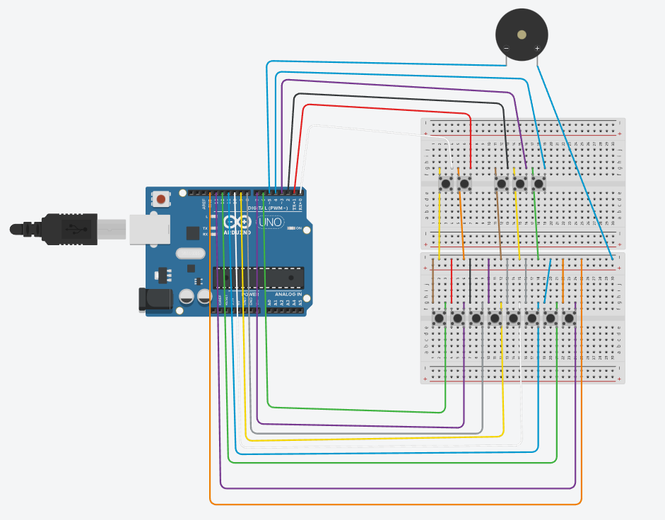
Here is the design of the circuit done in Tinkercad.
Notes
1] Top left of all switches connected to negative of breadboard
2] Negative of breadboard connected to ground
3] Top right of all switches connected to respective arduino pins
4] The top row of five push buttons corresponds to all black keys while the bottom row of eight push buttons corresponds to the white keys in an octave starting from C in proper order from left to right.
5] Positive terminal of buzzer connected to negative of breadboard
6] Negative terminal of buzzer connected to arduino pin.
2 Likes
Documentation for the Makers Space Workshop
Done by Akshay Shanbhag of IISER Pune
Topic- To generate a DIY music synthesizer for one octave
Day 1-
1] Generated music using a push button, in the form of
a] One notes
b] Multiple notes
when button is pressed
All done using Arduino board and IDE
Day 2
1] Assignment of different music notes to different push buttons.
2] Creation of a music octave starting from C and ending at C in increasing order of frequency. 13 push buttons and speaker used.
All done using Arduino board and IDE
Day 3
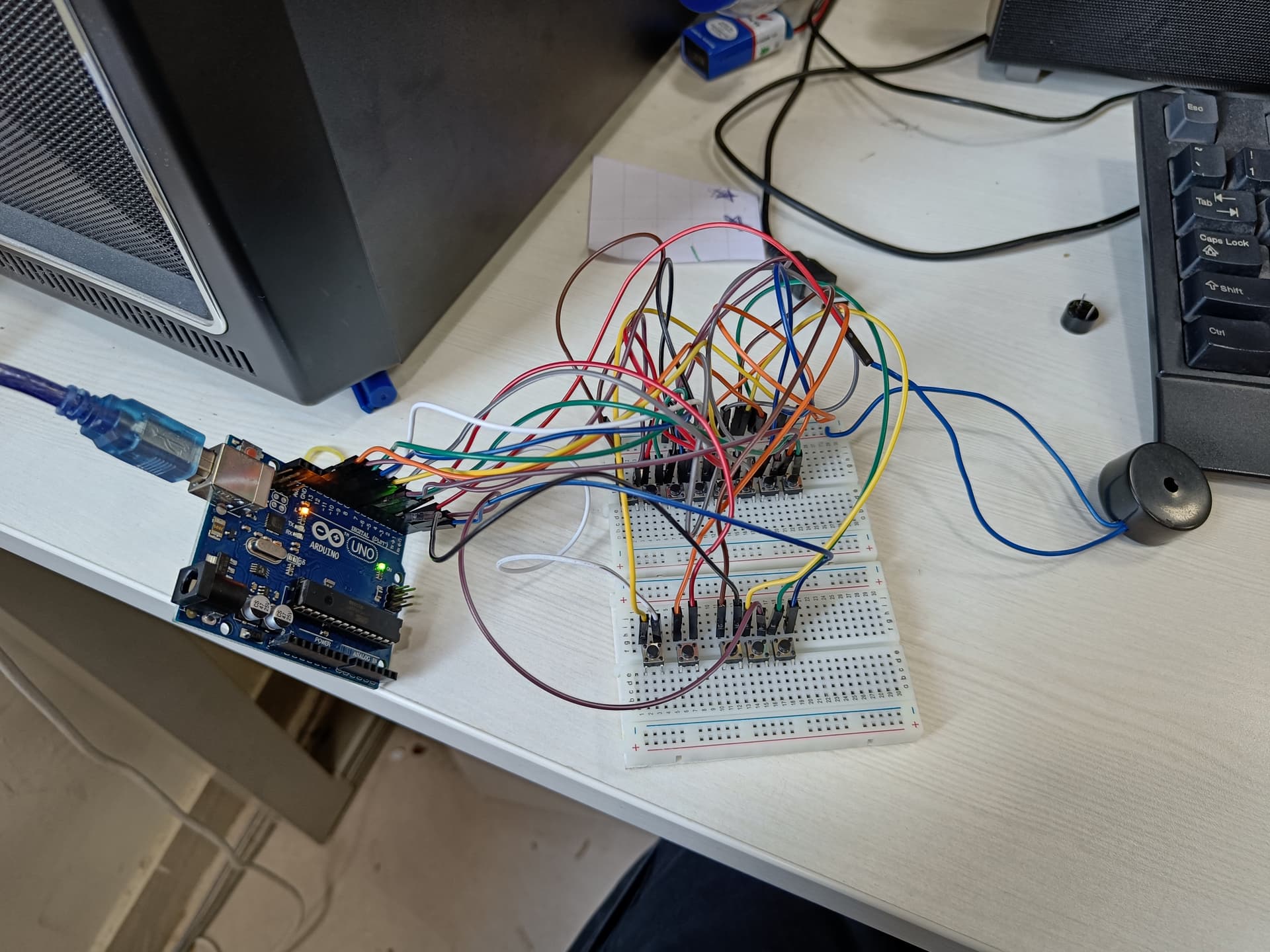
1] Prototype of music synthesizer of one octave- building begins.
2] All requisite components (wires, push buttons etc.) soldered to prototype board.
3] Outline of keyboard marked on foam board and cut.
Day 4
1] All components laid flat on another board.
2] Outline of keyboard attached to push buttons at the right positions.
3] Music system made independent of computer system by attaching battery and adapter in place of the Arduino USB cable.
4] Final prototype complete for one octave.
2 Likes
Documentation for the Makers Space Workshop
Done by Akshay Shanbhag of IISER Pune
Topic- To generate a DIY music synthesizer for one octave
Day 1-
1] Generated music using a push button, in the form of
a] One notes
b] Multiple notes
when button is pressed
All done using Arduino board and IDE
Day 2
1] Assignment of different music notes to different push buttons.
2] Creation of a music octave starting from C and ending at C in increasing order of frequency. 13 push buttons and speaker used.
All done using Arduino board and IDE
Day 3
1] Prototype of music synthesizer of one octave- building begins.
2] All requisite components (wires, push buttons etc.) soldered to prototype board.
3] Outline of keyboard marked on foam board and cut.
Day 4
1] All components laid flat on another board.
2] Outline of keyboard attached to push buttons at the right positions.
3] Music system made independent of computer system by attaching battery and adapter in place of the Arduino USB cable.
4] Final prototype complete for one octave.
2 Likes
Images of the prototype
Before assembly
https://drive.google.com/file/d/1ufLiI-amKPwXSzBIFC3K5KE1oQ8fxHz3/view?usp=sharing
After assembly
https://drive.google.com/file/d/1upyKs91kuFu65TgqqFDZsHNobDUuKtPu/view?usp=sharing
2 Likes

The link for my presentation recorded. Credits- Renuka sir.
Sorry for the delay.
2 Likes
+1. Cannot grant badges for a non text. The text post is likely to win multiple badges.
Final Documentation of the workshop
Done by Akshay Shanbhag of IISER Pune
Topic- To generate a DIY music synthesizer for one octave
Progress of Project
Day 1-
1] Generated music using a push button, in the form of
a] One notes
b] Multiple notes
when button is pressed
All done using Arduino board and IDE
Day 2
1] Assignment of different music notes to different push buttons.
2] Creation of a music octave starting from C and ending at C in increasing order of frequency. 13 push buttons and speaker used.
All done using Arduino board and IDE
Day 3
1] Prototype of music synthesizer of one octave- building begins.
2] All requisite components (wires, push buttons etc.) soldered to prototype board.
3] Outline of keyboard marked on foam board and cut.
4] Design of prototype on Tinkercad, such that no wires cross each other.
Day 4
1] All components laid flat on another board.
2] Outline of keyboard attached to push buttons at the right positions.
3] Music system made independent of computer system by attaching battery and adapter in place of the Arduino USB cable.
4] Final prototype complete for one octave.
Regarding the circuit
1] 13 pushbuttons, wires, Adapter and 1 speaker used apart from a prototype board, Arduino Uno and solder gun. So 14 pins for digital input. This idea is hence an example of direct digital synthesis which is used to make music synthesizers such as these.
2] One side of all pushbuttons connected to ground
3] Another side of all pushbuttons connected to respective arduino pins
4] The top row of five push buttons corresponds to all black keys while the bottom row of eight push buttons corresponds to the white keys in an octave starting from C in increasing order of frequencies from left to right.
5] Positive terminal of buzzer connected to ground
6] Negative terminal of buzzer connected to arduino pin.
7] Following components soldered- All push buttons, wires to ground/ pushbuttons. These are soldered to the prototype board
8] 13 semitones = One octave, where semitone is the difference between a white key note and it’s corresponding sharp/ flat note.
9] Frequencies of each note are assigned in the code itself. For this octave the frequency of the first note is half of that of the last note.
10] Foam board used in making the keyboard outline (as it’s durable and of good quality) and stuck using two sided tape.
11] The sound of that note will go on as long as I keep the pushbutton corresponding to the note pressed.
1 Like
I have successfully added the solar cell and displayed it on science day. The documentation and the circuit are given in the pdfs below.
ACTUAL CIRCUIT.pdf (824.3 KB)
SCIENCE DAY 2023 Documentation.pdf (21.4 KB)
1 Like