Hello everyone,
Today, we are gonna be making a sequential led blinking circuit with Arduino Uno.
For this you require,
1.Arduino Uno r3
2.Data cable to connect Arduino with laptop or pc
3.5 LEDs (Colour of your choice)
4.1 Breadboard
5.16 male to male jumper wires
6.A 5v power source
7.Arduino IDE Software
Here’s the link to download it: https://www.arduino.cc/en/software: https://www.arduino.cc/en/software
The steps are:
1.Connect the digital GND pin of the Arduino to any of the power rail on the breadboard.
2.Next, connect the LEDs to the breadboard with the Negative (-) legs towards the left as shown in the image below: Screenshot_20210926-163620_Gallery.jpg - Google Drive
3.Now connect the Negative (-) legs of all the LEDs to the power rail on which you connected the GND pin of Arduino using jumper wires as shown in the image below: Screenshot_20210926-165212_Gallery.jpg - Google Drive
4.Now connect the 1st LED to pin no.13, 2nd LED to pin 12, 3rd LED to pin 11, 4th LED to pin 10
and the 5th LED to pin 9 using jumper wires as shown in the video below: 20210926_170726[1].mp4 - Google Drive
5.Now open the Arduino IDE software on your laptop or pc.
6.Now, you can copy and paste the code under the specified columns:
This is how the code should look:

This is the code: (above the void setup)
int LED1 = 13;
int LED2 = 12;
int LED3 = 11;
int LED4 = 10;
int LED5 = 9;
Now the code in the void setup() {
pinMode(LED1, OUTPUT);
pinMode(LED2, OUTPUT);
pinMode(LED3, OUTPUT);
pinMode(LED4, OUTPUT);
pinMode(LED5, OUTPUT);
}
Now the code in the void loop() {
digitalWrite(LED1, HIGH);
delay(200);
digitalWrite(LED2, HIGH);
delay(200);
digitalWrite(LED3, HIGH);
delay(200);
digitalWrite(LED4, HIGH);
delay(200);
digitalWrite(LED5, HIGH);
delay(200);
digitalWrite(LED5, LOW);
delay(300);
digitalWrite(LED4, LOW);
delay(300);
digitalWrite(LED3, LOW);
delay(300);
digitalWrite(LED2, LOW);
delay(300);
digitalWrite(LED1, LOW);
delay(300);
}
Remember:
- The code is case sensitive
2.Remember the semicolons ( ; ) after every line of code
3.Remember the braces ( { } ) after the end of void setup and void loop section.
4.As shown in the image which displays the code there are some lines written after slashes ( / ), they are not a part of the code.The Arduino doesn’t consider those lines, they are just for clarification.
8.After pasting the code, you can connect the Arduino to your laptop or pc using the cable provided with the Arduino.
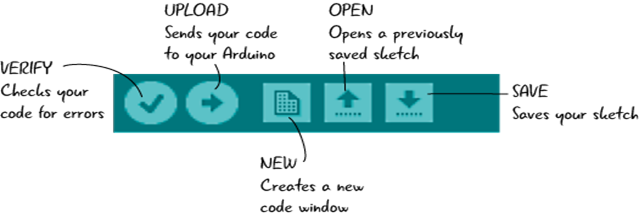
9.Now, click the upload button and if have pasted the code correctly, you are not likely to face any errors.
10.Now you it on using a 9v battery with a barrel jack adaptor or in this case I have used a 5v 1A adapter.
11.If you have done everything correctly it should work like this: