I Want To Make An Anemometer, Please help me in the connections of an Anemometer
4 Likes
Great to know that you want to join the project on building an anemometer. Please let us know if you have any experience with working with IoT, ardiuno and hall-effect sensors. Accordingly we could guide you.
2 Likes
Ya i was basics about Arduino and hall efect sensor
2 Likes
What is the part number of the hall effect sensor?
How many hall sensors will you use?
Doodle a schematic and post.
We will correct it if there are any mistakes
2 Likes
Yes, @Harshil to understand how you would like to go ahead, please send the design of your anemometer as a drawing. That will help us to support your project.
1 Like
sir i am following the design that we did in the stem workshop held at NMS Jaipur
1 Like
I’ll use only one hall sensor
2 Likes
How about using optical interface ( for example IR), Do you think this method of sensing can also be used?
Keep Exploring!
1 Like
sir i am following the design that we did in the stem workshop held at NMS Jaipur
2 Likes
should i send you the design again
1 Like
Better to doodle a single hall sensor and it’s connection.
Also post the hall effect sensor part number.
The part number will lead to a data sheet that will tell you the polarity (N or S or both) and type (analog and digital).
2 Likes
sir i’ll use an IR hall sensor
2 Likes
IR=Infra Red.
Hall sensor=magnetic field sensing.
Are you sure that you are using IR hall sensor?
2 Likes
sir I Was there in the stem workshop and I know what is a anemometer but I want to know about the connection
2 Likes
you can even use a IR groove sensor
4 Likes
Yes, am using the IR groove sensor only
1 Like
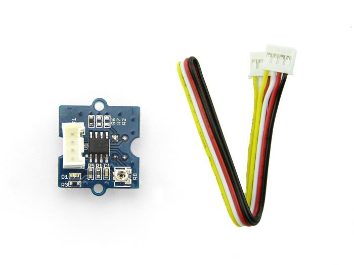
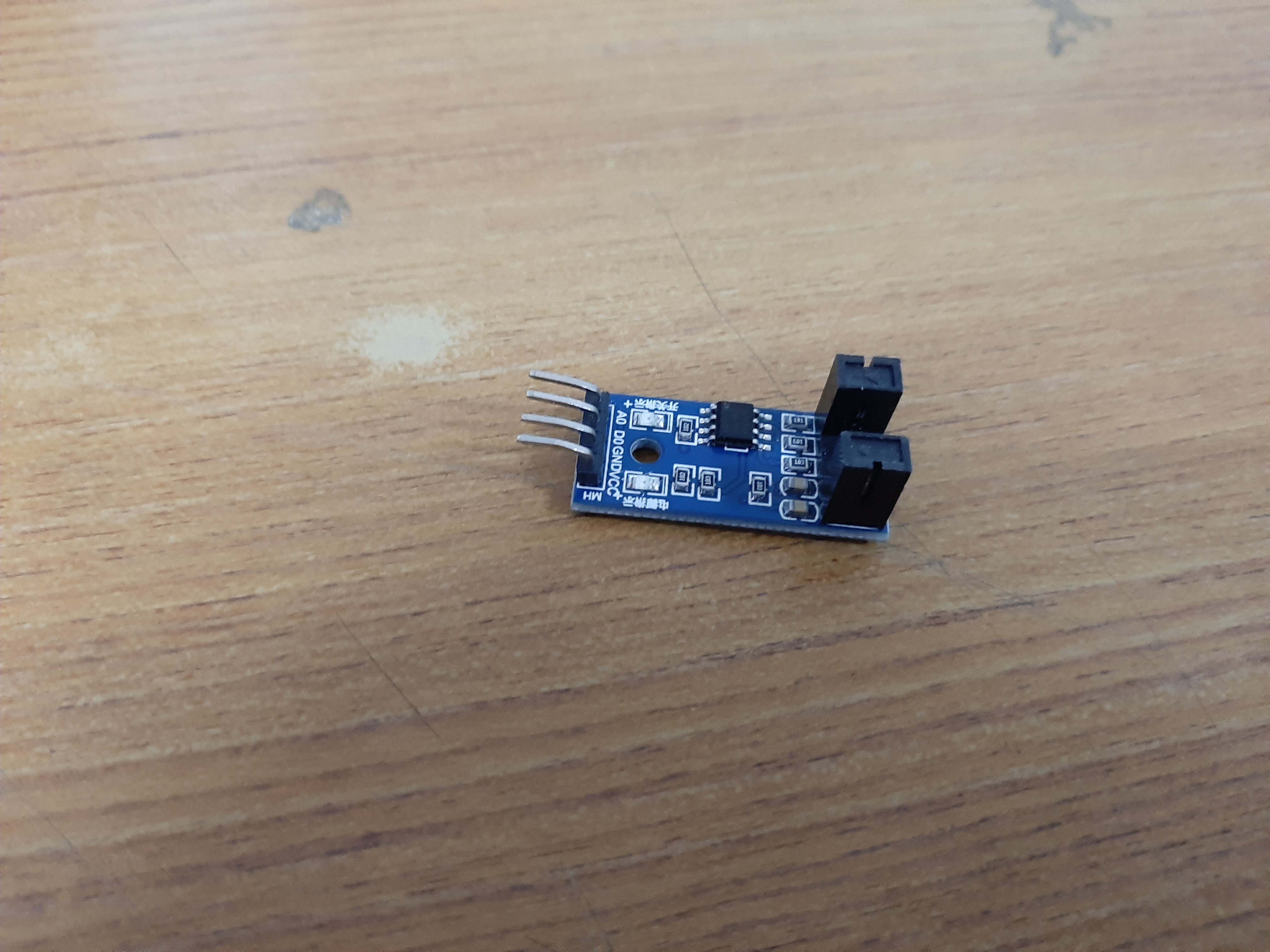
The IR groove sensor is a reflective sensor. Using such a sensor will change the design slightly from the anemometer shown at Jaipur workshop and would be a wonderful design variation.
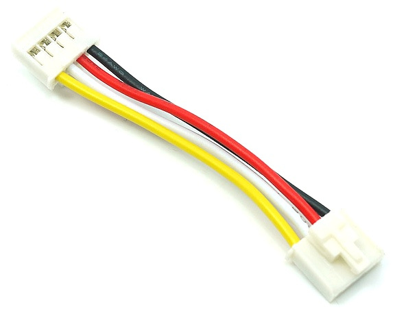
Groove connector:
Pin 1 signal ouput Yellow
Pin 2 NC (no connection) White
Pin 3 VCC (3.3 or 5v) Red
Pin 4 ground Black
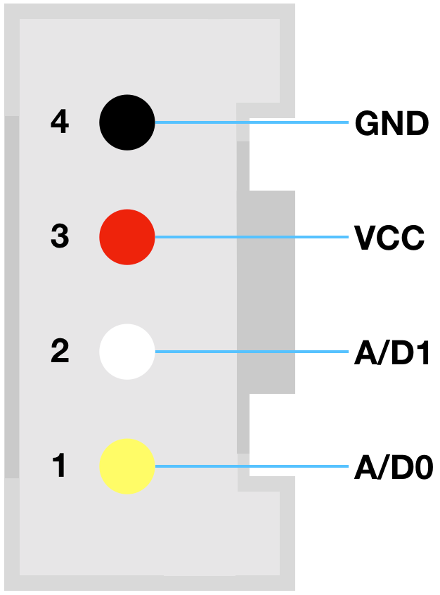
Pin 1 will connect to the pin that you are using on arduino. Any digital pin will work. Just make sure your code uses the right pin name.
3 Likes
Thanks A Lot Sir For Guiding Me
Will Revert Soon ![]()
![]()
2 Likes