Can you shre the stl file for windvane design for 3d printing?
2 Likes
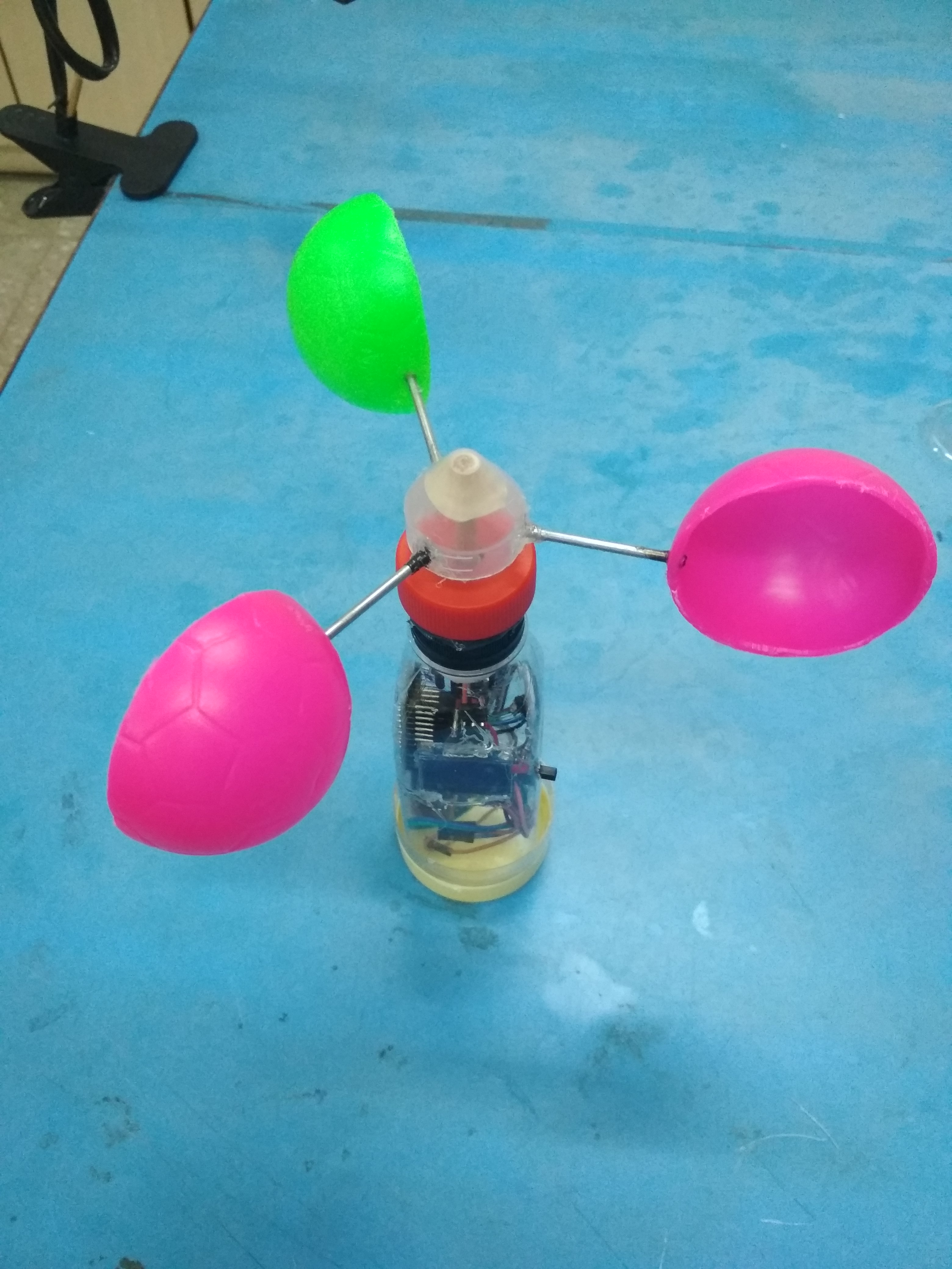
There are various types of anemometer, but the one which we have used here is called Cup Anemometer.
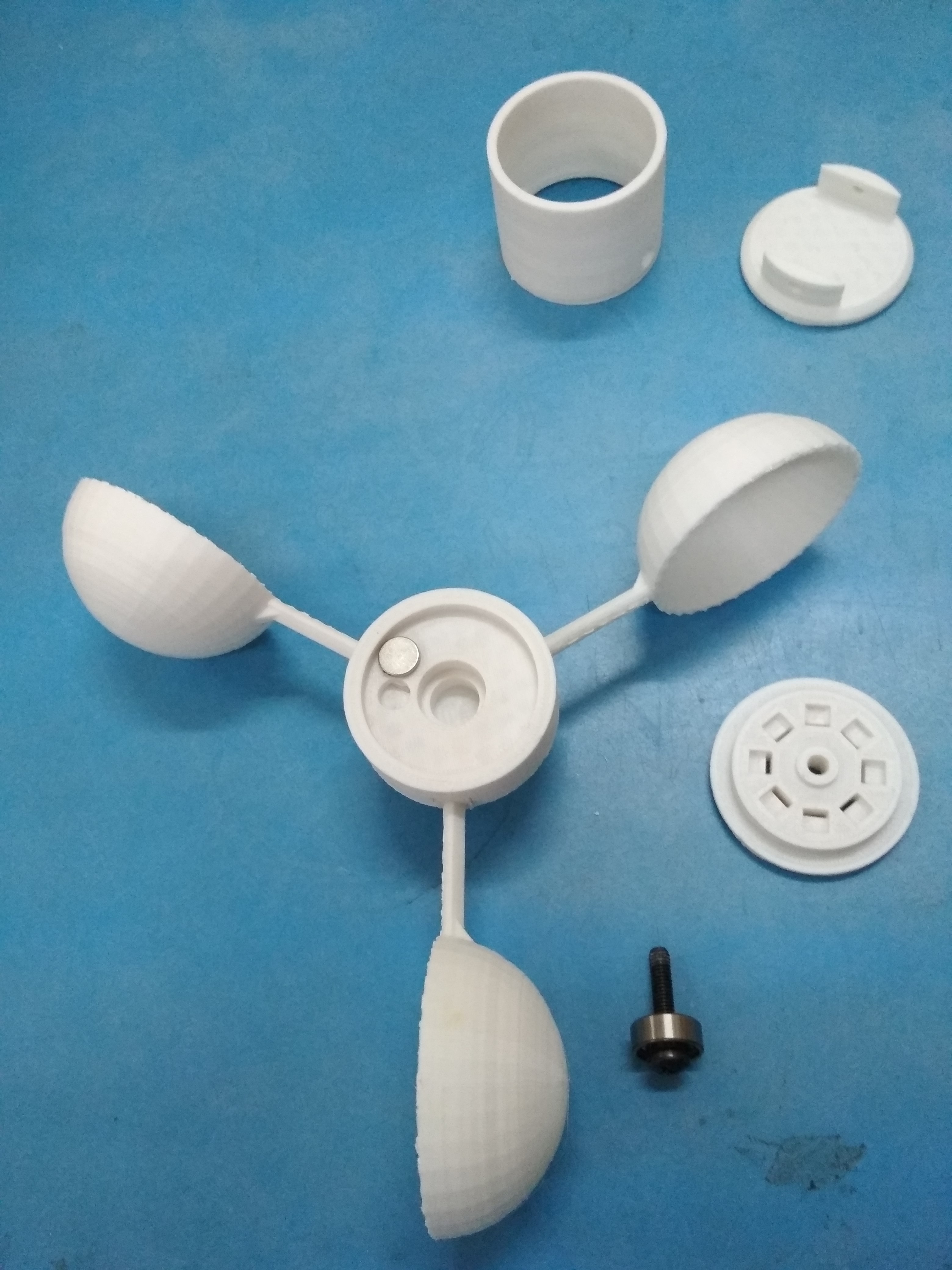
In Cup Anemometer 3 hemispherical cups are mounted on one end of 3 arms (4 cup and 4 arms are also used), these arms from other hand are also mounted at equal angle to each other on a vertical pole with rotating mechanism. Mainly smooth bearings are used for rotating mechanism.
When air start passing across the cups horizontally, these cups collects the air which makes cups and arms attached to vertical pole (we call it rotating assembly) starts rotating. And these rotations are proportionate to wind speed.
For finding the average wind speed, rotations are observed for over a period of time.
So how to monitor each rotation?
Well, there are two ways, Optical method and other is Magnetic method.
Optical Method.
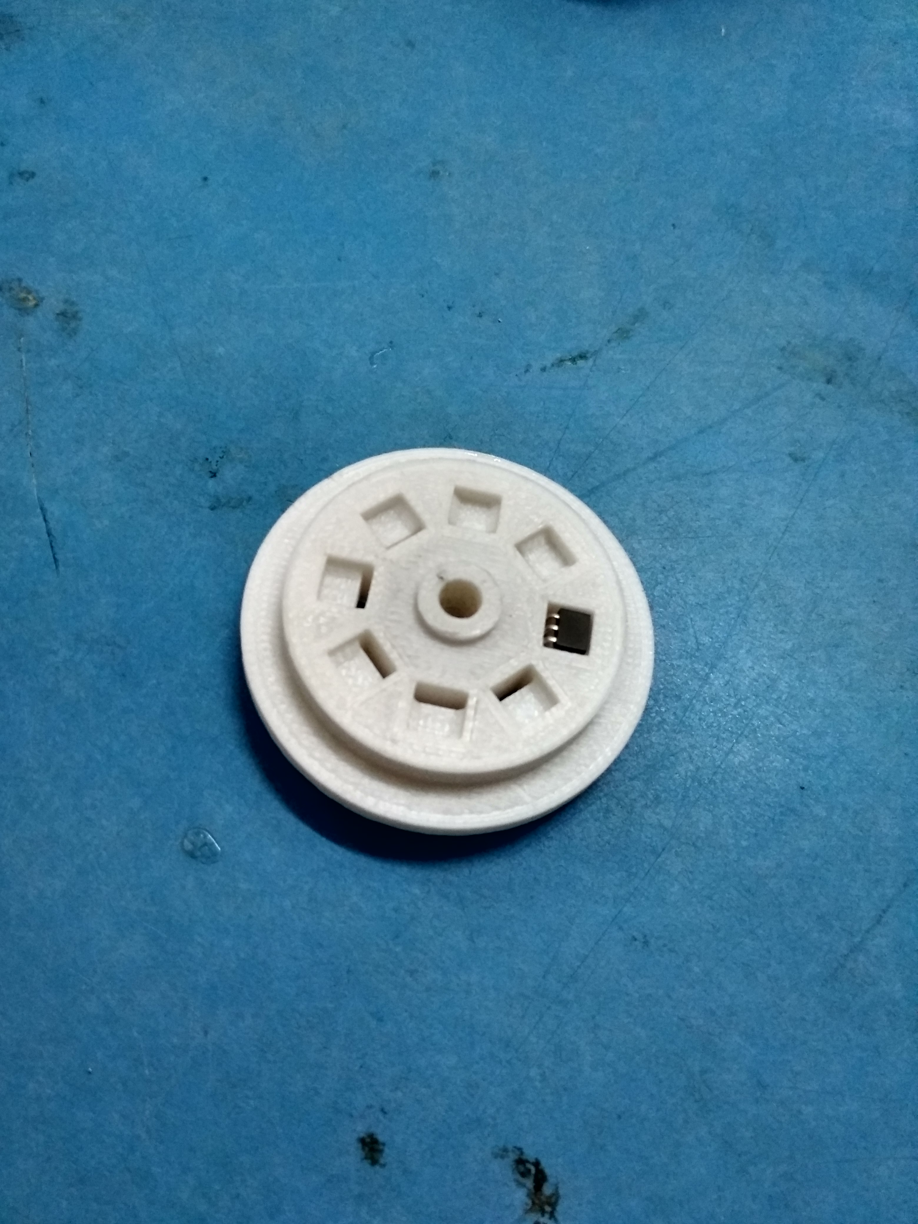
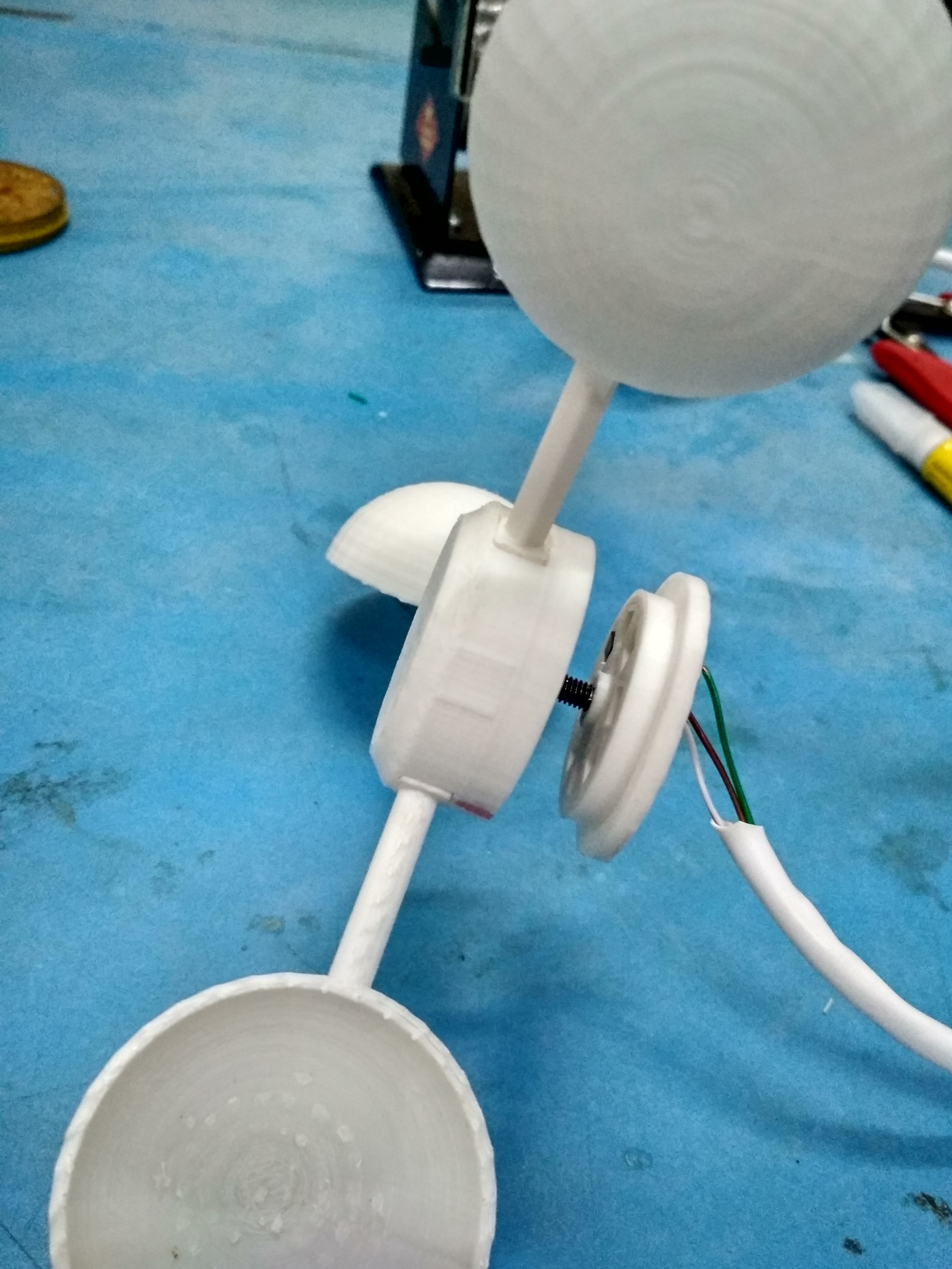
At the top end of vertical rotating pole we have cups attached through arms, in the same manner there is a small cap consist of one or more tooth is connected to bottom end which cuts the optical path of IR led and receiver and for each it gives out a pulse.
In this image you can see at bottom end we have a cap with few tooth.
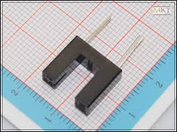
In this image there is an IR sensor with groove through which tooths are passes.
Magnetic Method
In this method instead of IR groove sensor and tooth cap, either reed switch or hall sensor and magnet is used, magnet is attached with the rotating assembly and whenever it passes through reed switch or hall sensor it gives a pulse.
Hall Sensor
We can even place more than one sensor.
So both method gives us a pulse or few pulses for each rotation and are counted by a microcontroller (here we are using Arduino Board) over a period of time.
While designing and implementing, there are various interesting questions comes into action.
- From top view what shape will rotating assembly form?
- At what angle each cup via arm will be mounted on vertical pole?
- Once the angle is calculated, how actually cup via arm will get mounted on vertical pole?
- What is one rotation and how much distance will it cover in one rotation?
- What is the impact of placing more than one tooth or hall sensor?
- *How to calculate the wind speed? *
- How to define a period of time for monitoring rotations?
- How to calibrate the device?
- What is best method to monitor each pulse without missing any in microcontroller?
- How to code a mathematical calculation and calibration factor for wind speed?
Just start hands on with your own Anemometer and lets explore and discuss answers for each questions.
Happy Exploration and Making! 
4 Likes
Two questions are asked one for Rain Guage and another for Anemometer. ![]()
2 Likes
Image of photo interrupter.
On one side a LED is fixed. The opposite side has a phototransistor. The tiny slit prevents stray light from producing a false trigger.
A slightly different photo sensor. This one is a reflective photo sensor.
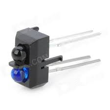
Can a reflective photo sensor be used in an anemometer.
Has anyone opened an old mouse with the small silicon rubber ball?
What mechanism is used there?
1 Like
We have used Wind Vane, Rain Guage and Steveson Screen design from Thingiverse.
The designs links are
Happy Making! ![]()
2 Likes
This is a very elaborate help. Thanks @Ashish_Pardeshi. I am sure the more we dig this , there will be more questions. Also, when we start making them like you do, we will revert back with questions.
1 Like
What is the working principle of wind vane?
2 Likes
Though @Ashish_Pardeshi or @jtd are the best to answer this question, let me guess:
The vane aligns in the direction of the wind, because it is free to rotate. The shape of the vane is such that the direction can be determined due to the fin present on one side. We need to calibrate the vane position to say North-south, then we can approximately find the direction in relation to the fixed direction based on angle of deviation from the marked position. The resolution can be increased by placing more magnets on the rim.
Gurus, please correct me.
3 Likes
Your answer is spot on @GN
1 Like
We have upgraded the design of Weather Station Shield (especially resolved the power issue), you can follow it here:
Weather Station with new shield was redeployed on 2019-07-26T18:30:00Z and it was working fine there was no shut down observed up to 2019-08-03T18:30:00Z and it was continuously streaming weather data on our server.
But Streaming weather data suddenly stopped from 2019-08-04T18:30:00Z.
We checked out our server, but everything was fine on server side. Now there was a need to get onto the site of weather station, we went and witnessed the following
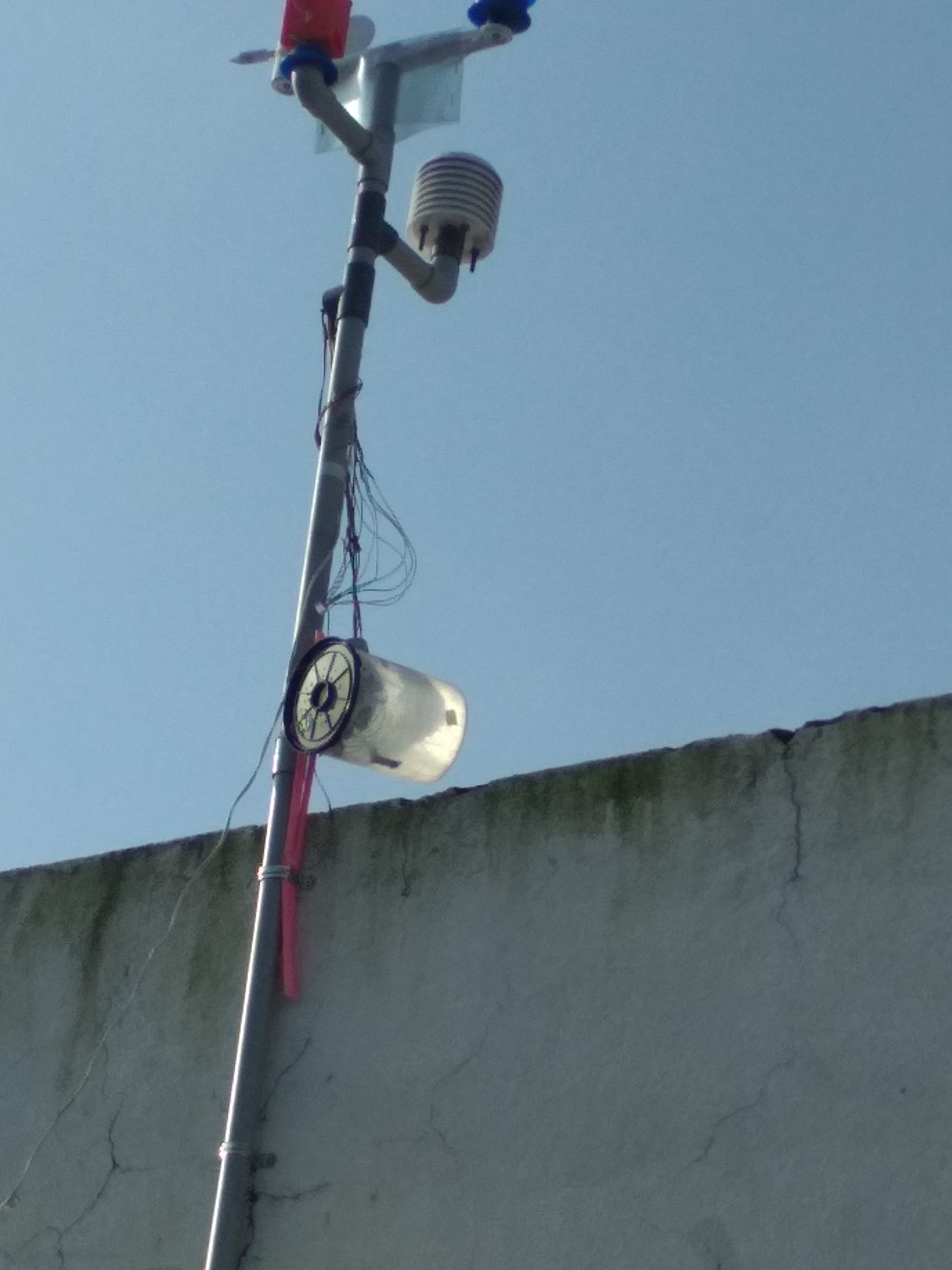
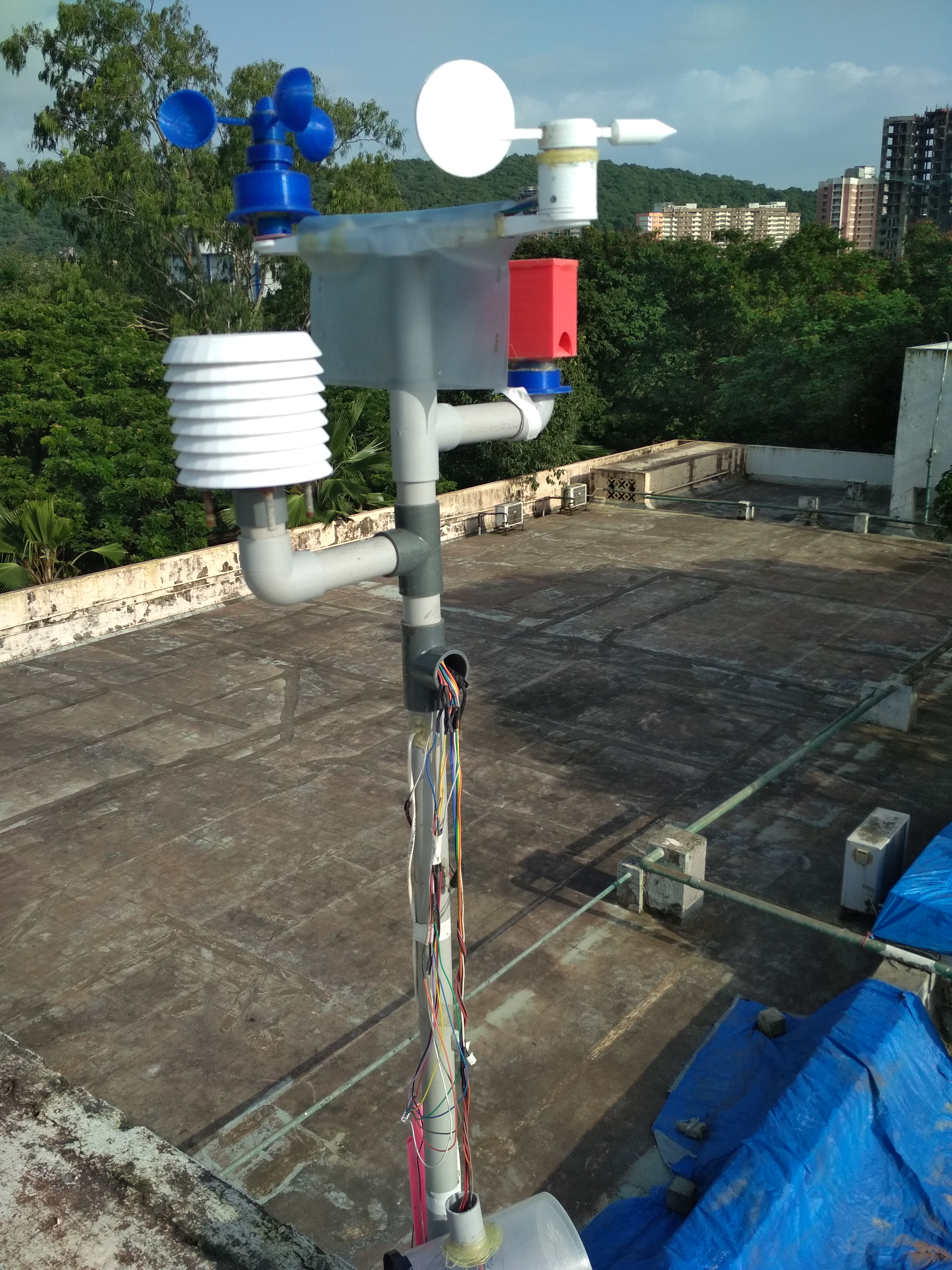
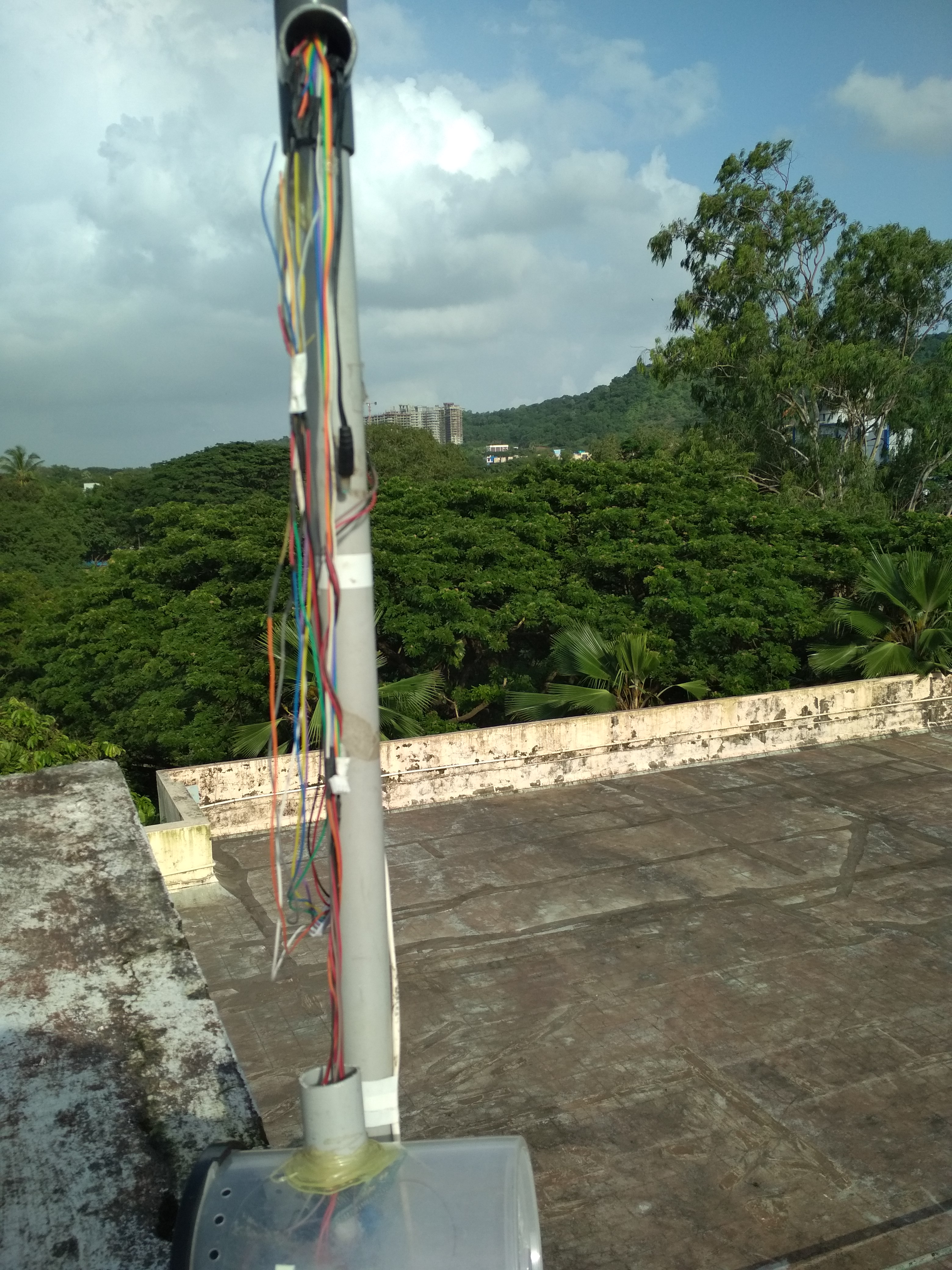
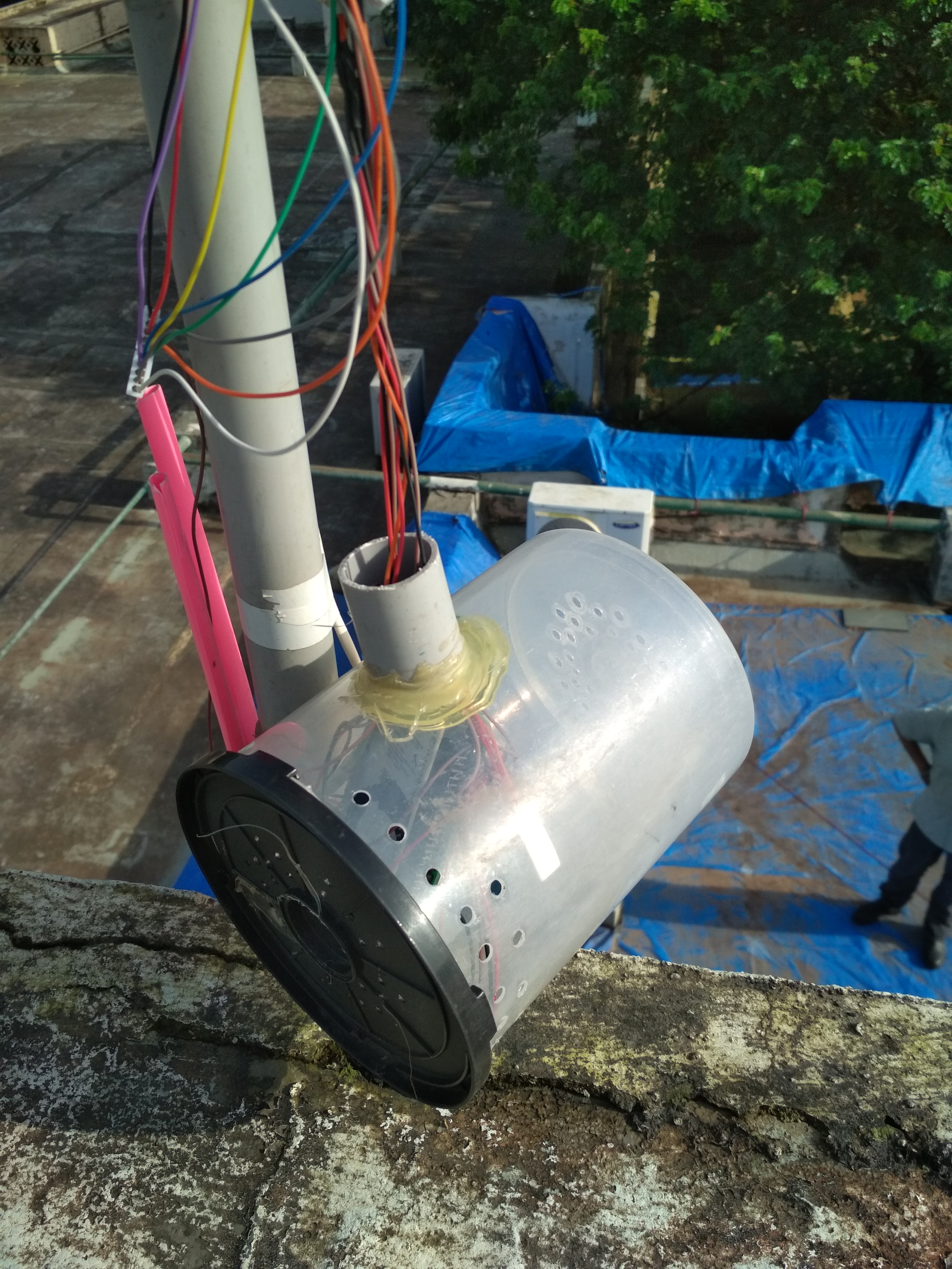
This is something strange and once again we got the failure of weather station, Most probably this is because of the heavy wind gust and there may be little chance of monkey tried to tinker the device.
Is this really a Failure ? No not at all
In fact this is the learning for us, to improve the weather station structure and need for making it more sturdy and completely weather proof . Once again time to brainstorm on following points.
-
Sturdy Weather Station Structure which can stand even with heavy wind gust.
-
Keeping control unit (Electronics) box rain as well as heat proof, there must be sufficient air circulation through the box.
-
Should deployed weather station be visible from ground, so that we can get immediate
response for any physical/mechanical damage to it.
It will be great if we discuss such issues and contribute ideas to resolve such problems in future.
Happy Exploration & Making!
2 Likes
@Ashish_Pardeshi
I had a question regarding the anemometer code.
Can you please share the code for the same?
Hi Vikram
Try to refer the code from below link as an reference:
3 Likes