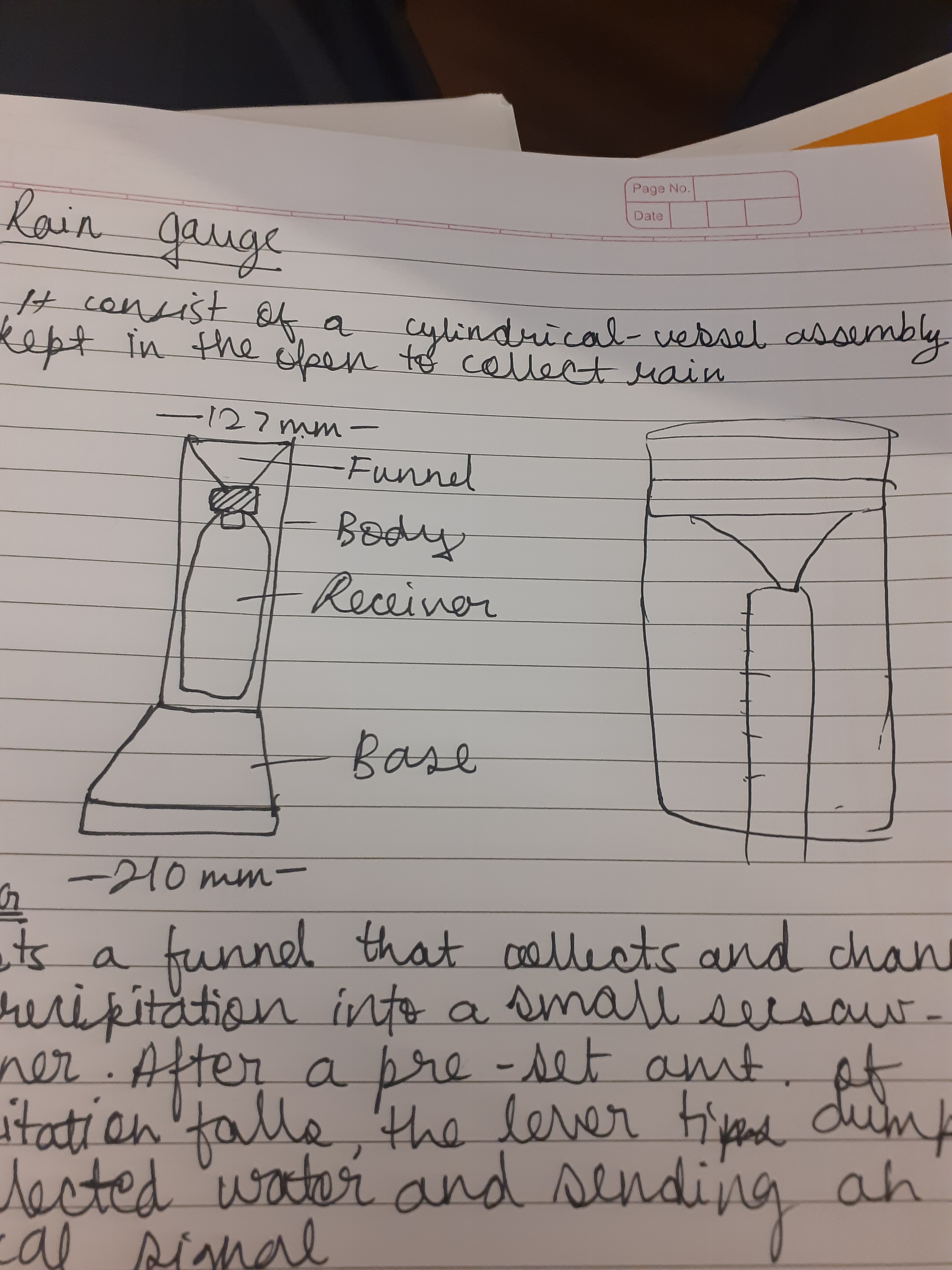
The challenge is to measure how much water is falling at the time of rain. The drops of rain vary from place to place as well as the size and density of drops.
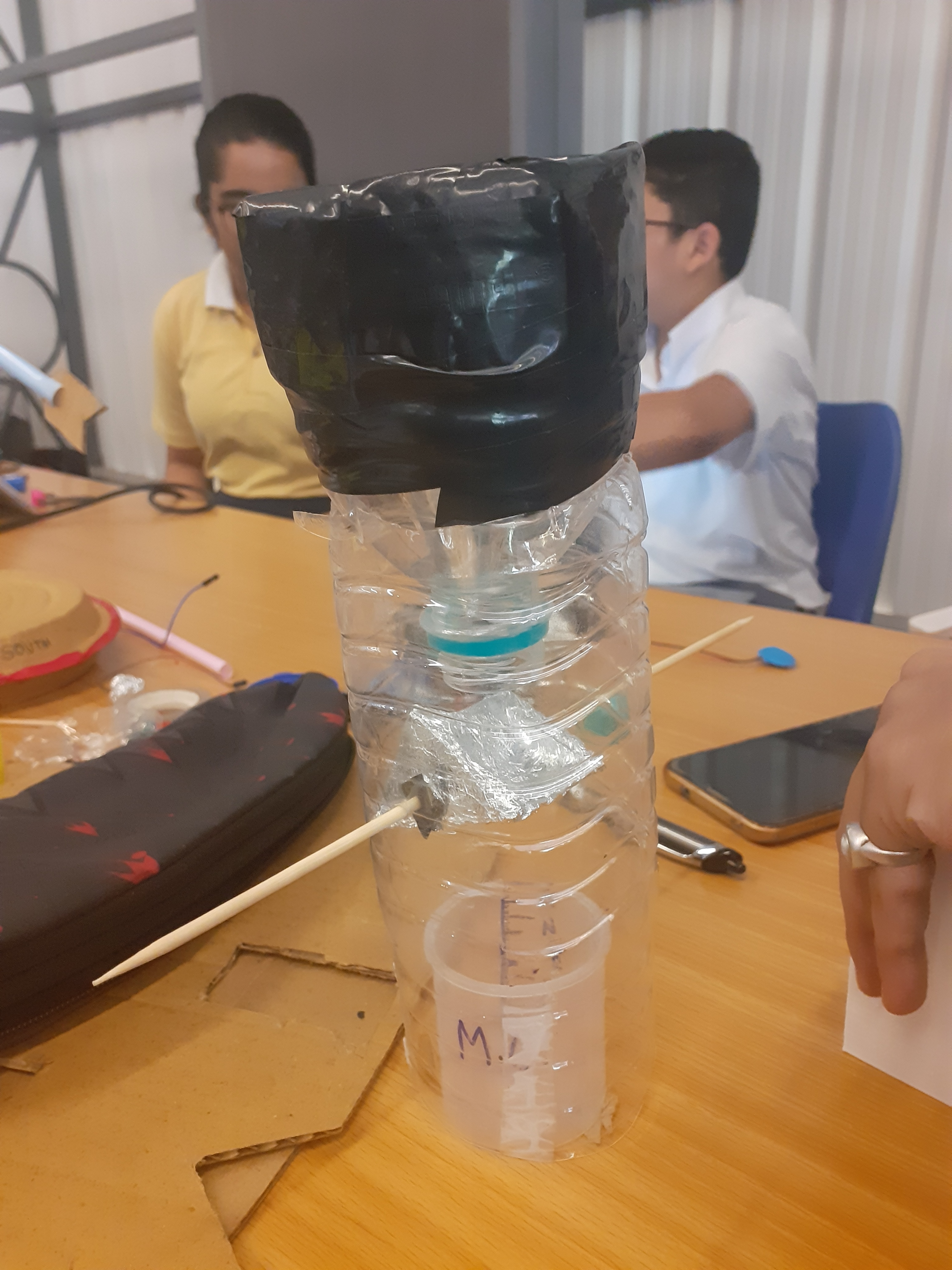
The standard model of measuring is to collect fallen rain water in a measuring cylinder. In this model we have manualy remove the fallen rain water from the cylinder. Therefore we need to design an instrument that does not need any human attention.
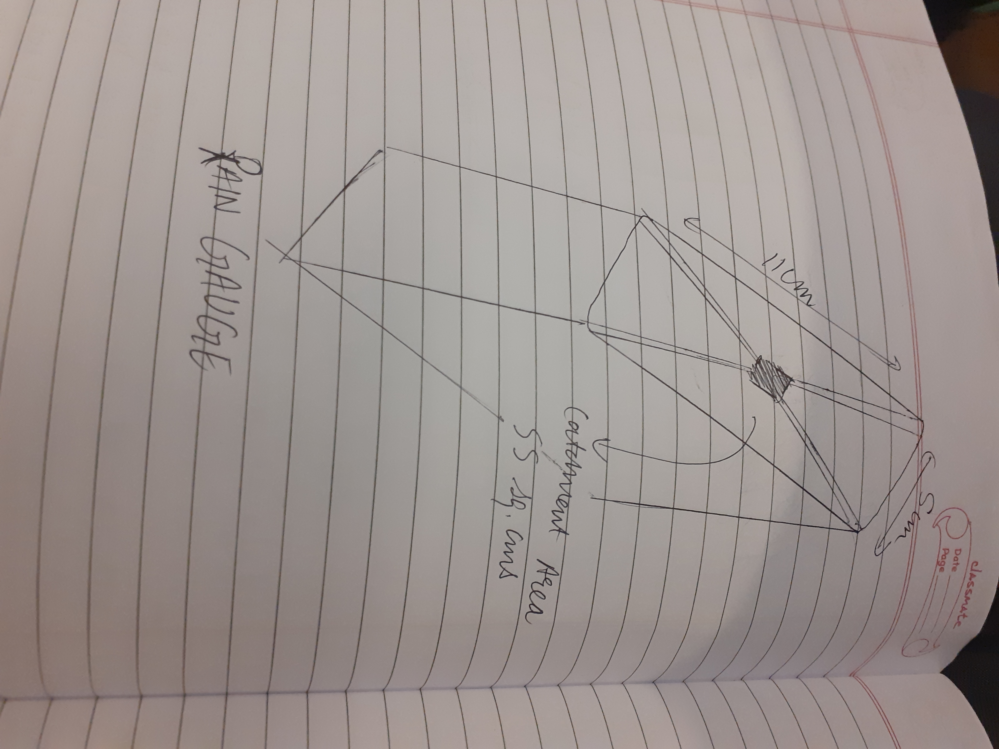
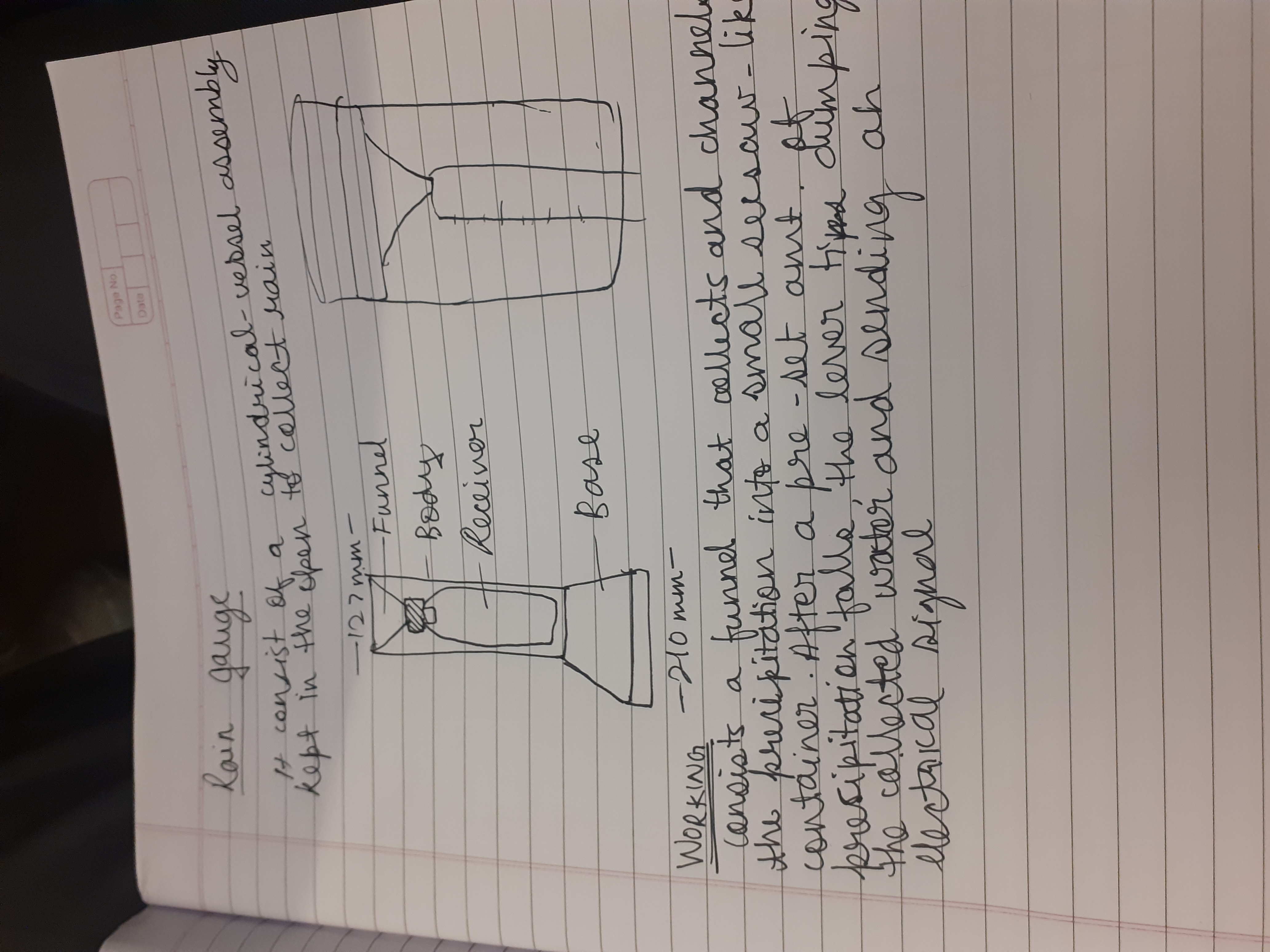
Rains are measured in milimeters on earth surface using a device known as Rain Guage. So the current challenge in this project is to make a IoT Rain Guage that doesnt need human intervention and measures and sends the data to IoT server. For this automation we could use electronics and communication technologies.
There are various methods and mechanism to measure Rainfall, just go through the below link to know more about it.
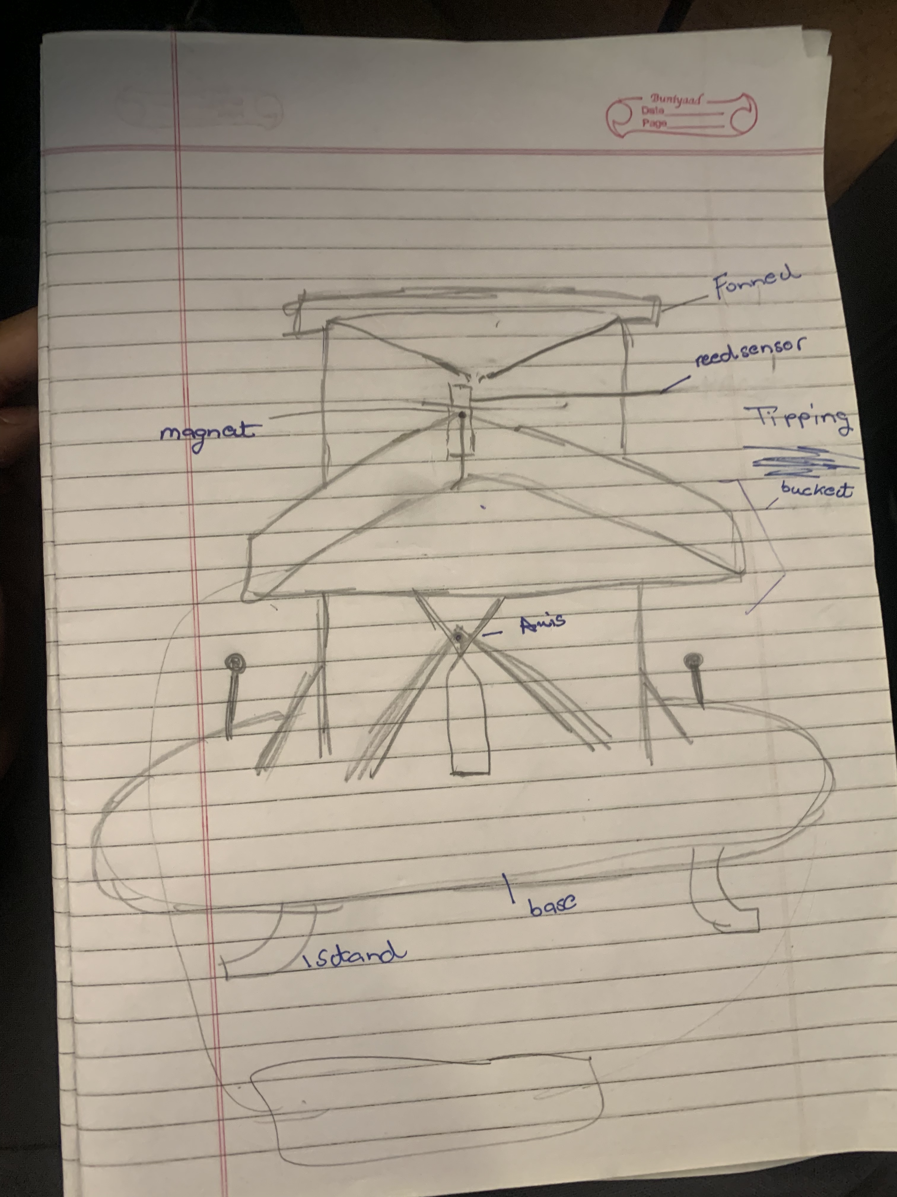
Picture shown below is of Tipping Bucket Mechanism Rain Guage.
The working of the simple rain gauge is primarily based on the principle of the tipping bucket mechanism where the water falls from the top into joint buckets evenly balance on an axle and the water uneven the balance and makes one bucket tip to the side and this is a respected process and a magnet on the centre repeatedly moves and then activate the hall sensor in the center to increase the value everytime.this occurrence o the tip and the rate by which it occurs is recorded by a sensor.Hence, calculating the amount of rainfall. @sambhav_jain @eklavyatyagi6 @Kushagra
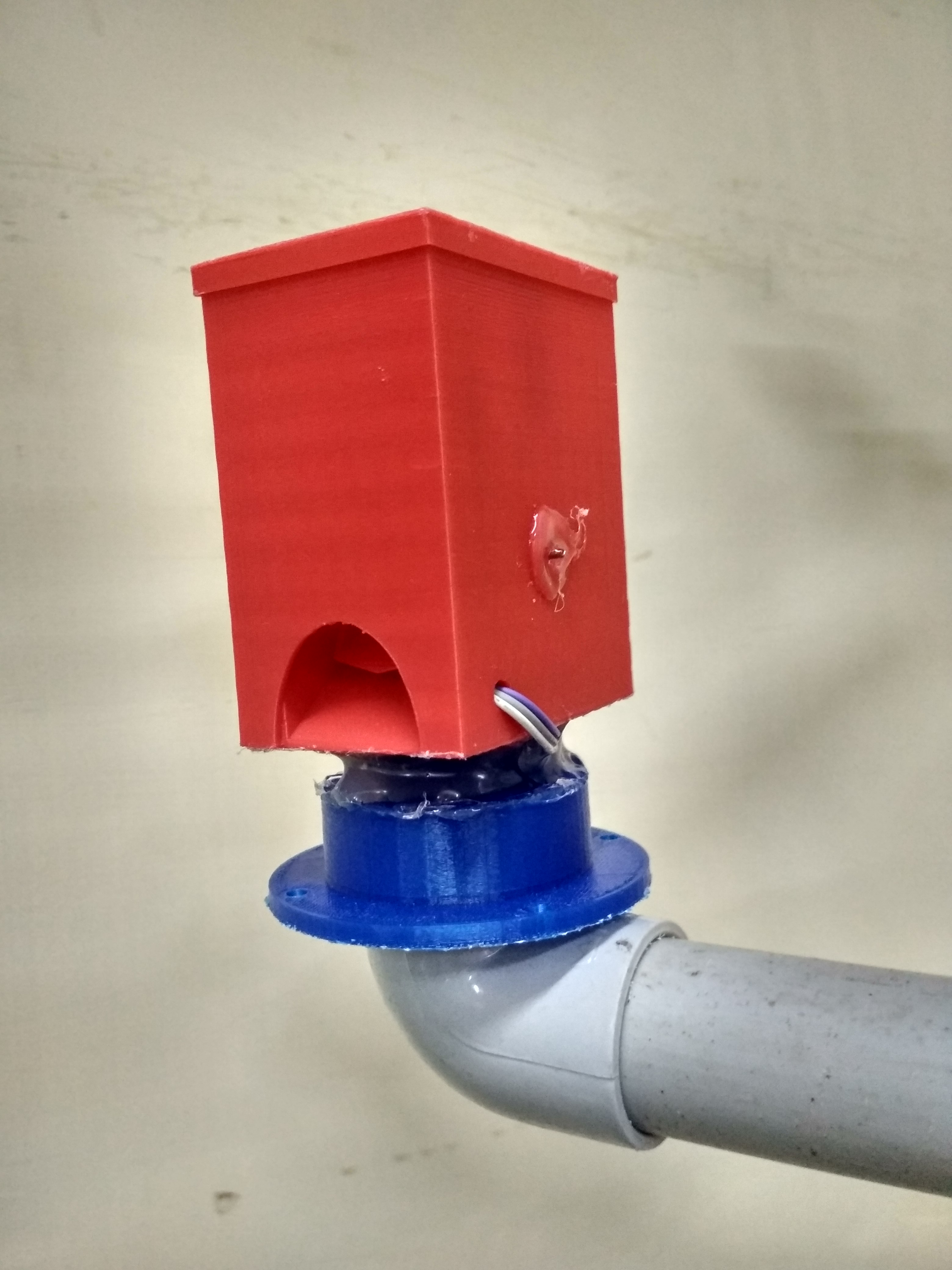
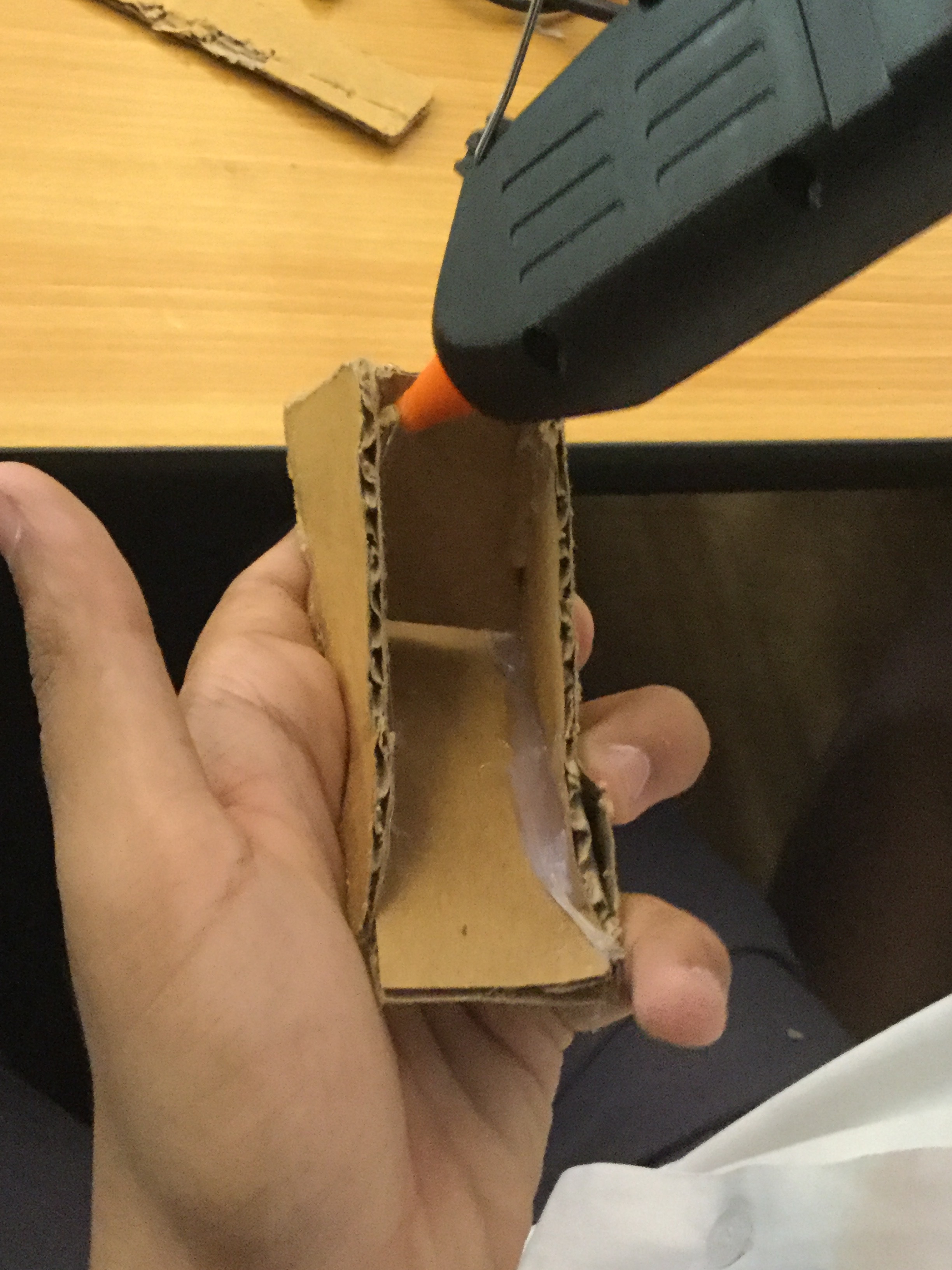
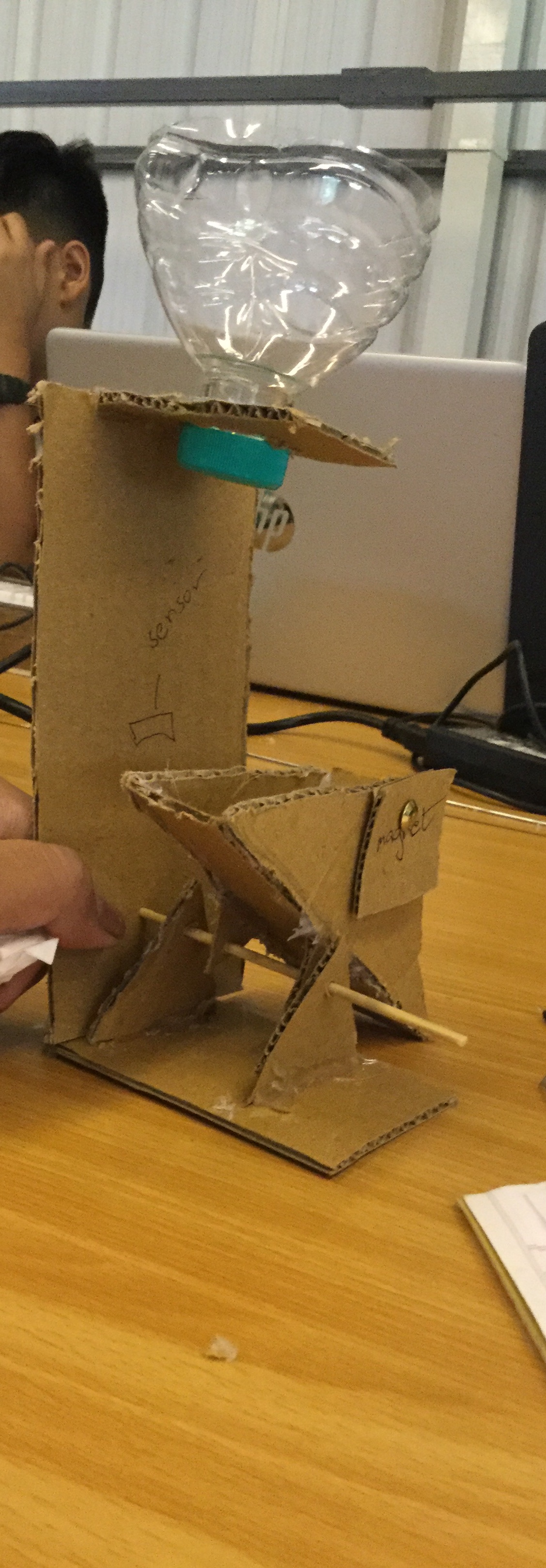
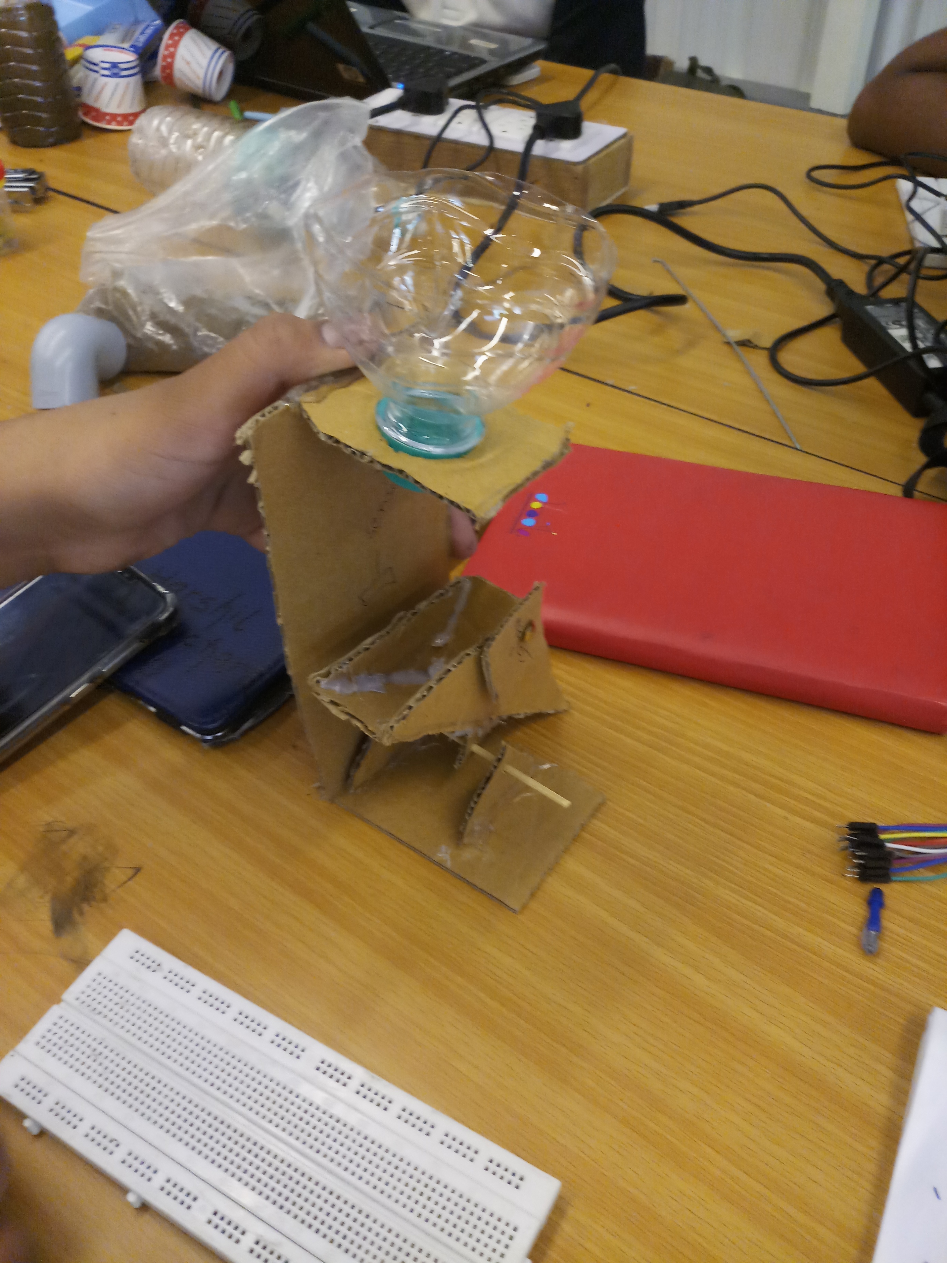
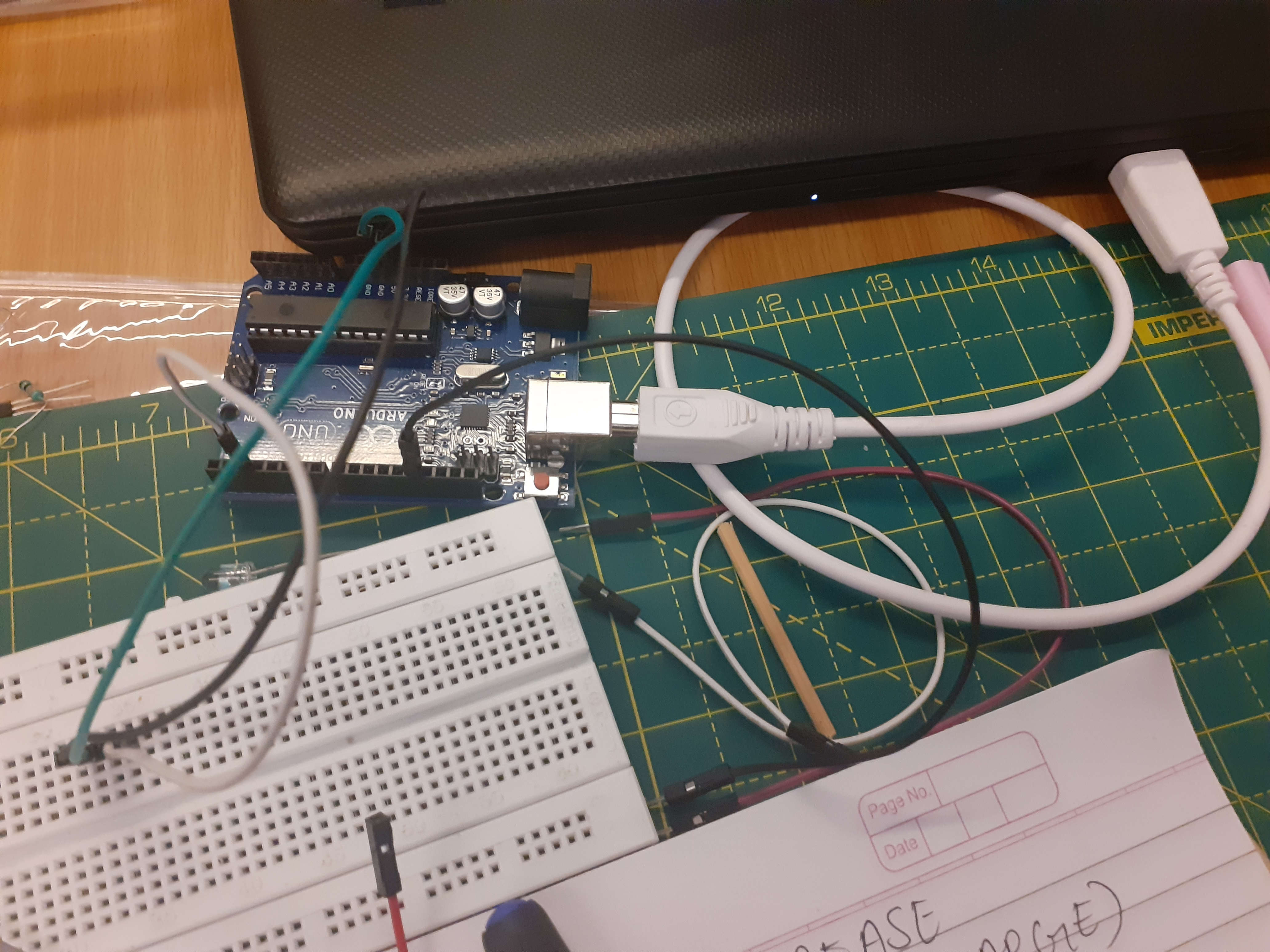
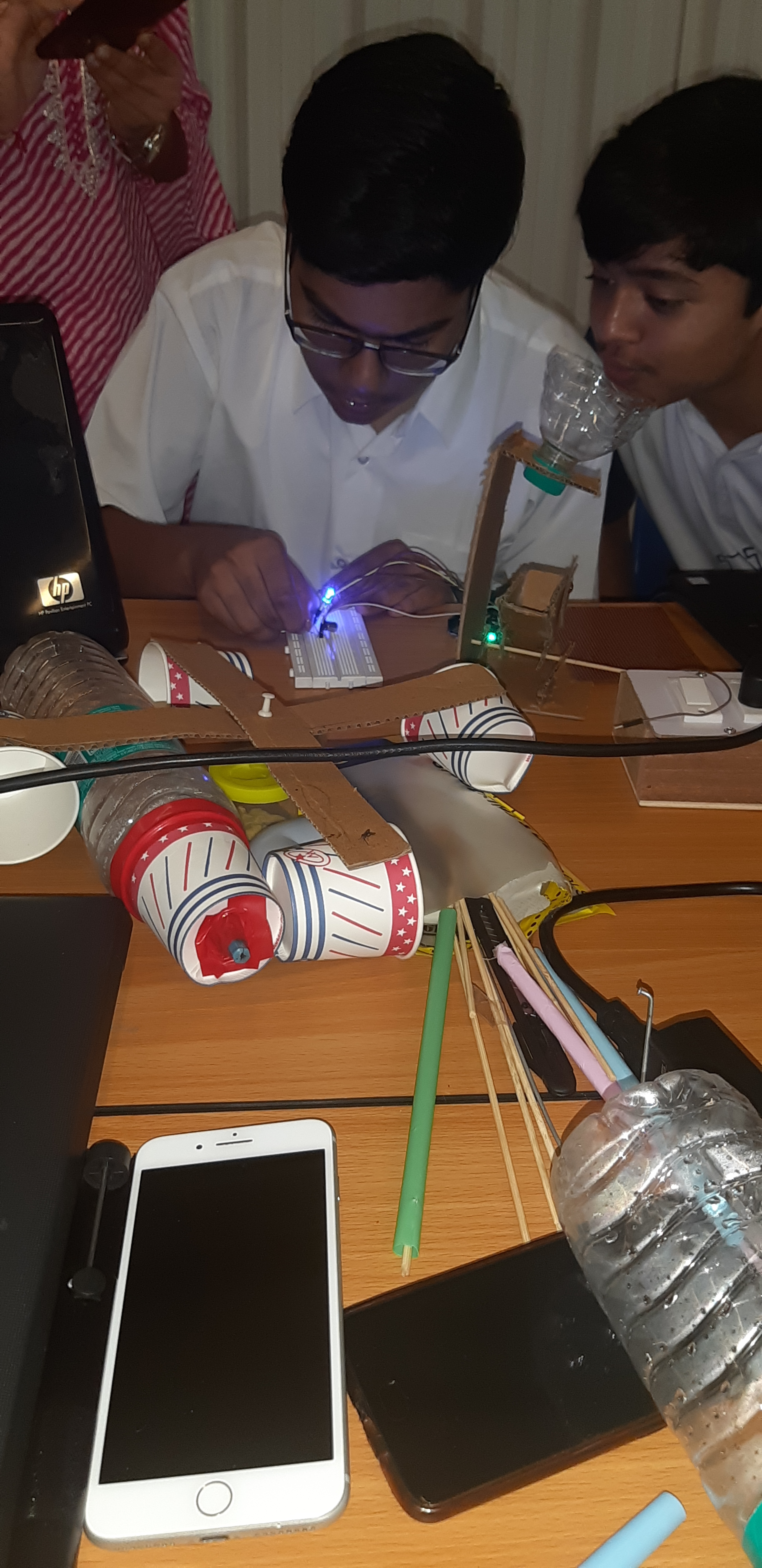
@suryamg@Lakshyanms@shivanibawri@Vedansh_2006@Shubhankar( group 7) We have made this demo model for our rain gauge which consists of the measuring cylinder, tipping basket, and the funnel. The ardiuno that will count the rainfall is given separately.
What are the components called?
What are their functions?
What is the function of this electric circuit?
Does a drawn electric circuit have another more commonly used name /names?
Can you explain how this works?
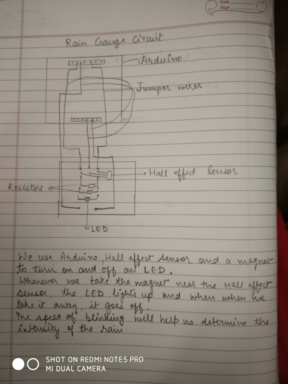
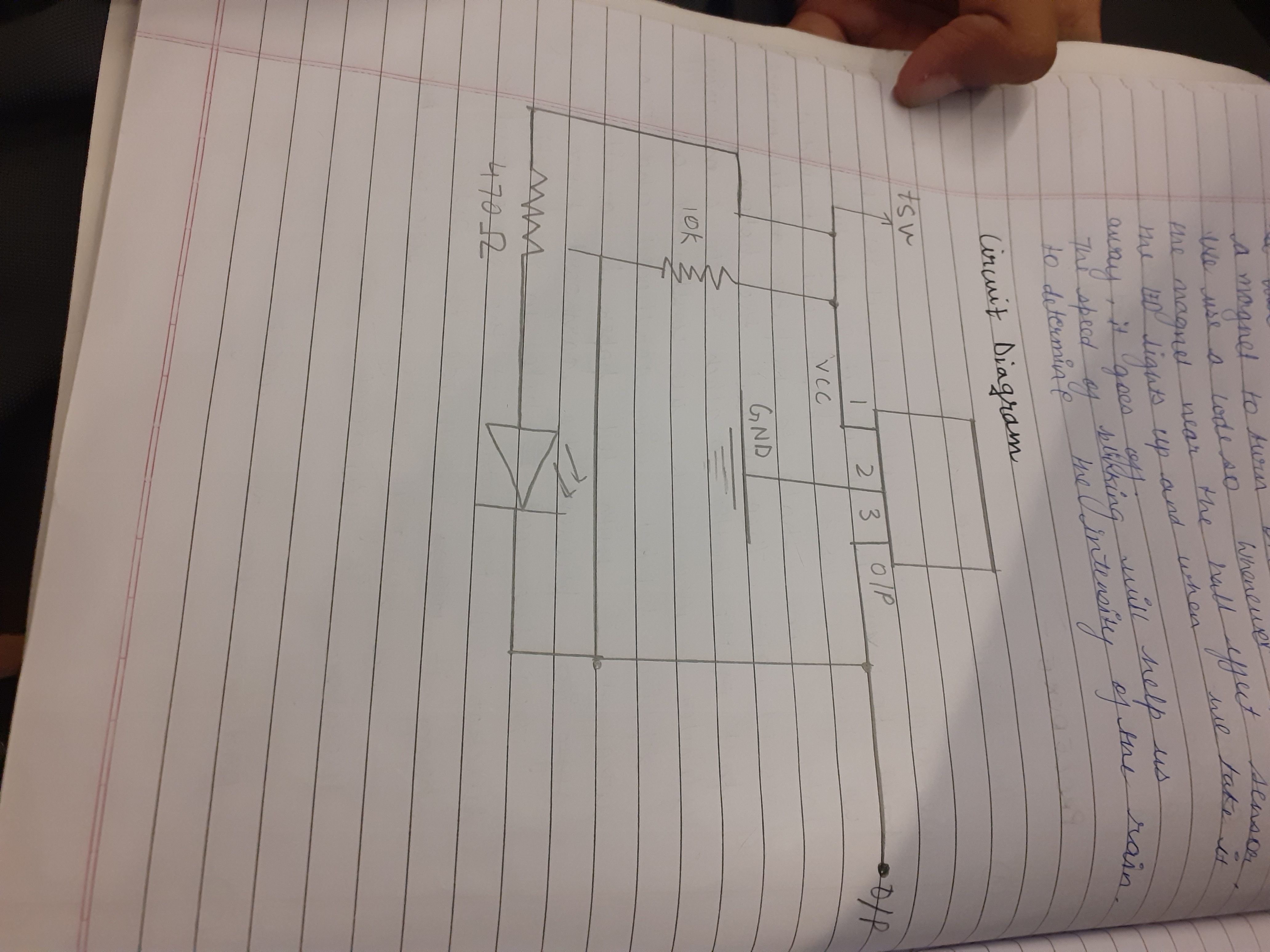
The components used in this circuit and their functions-
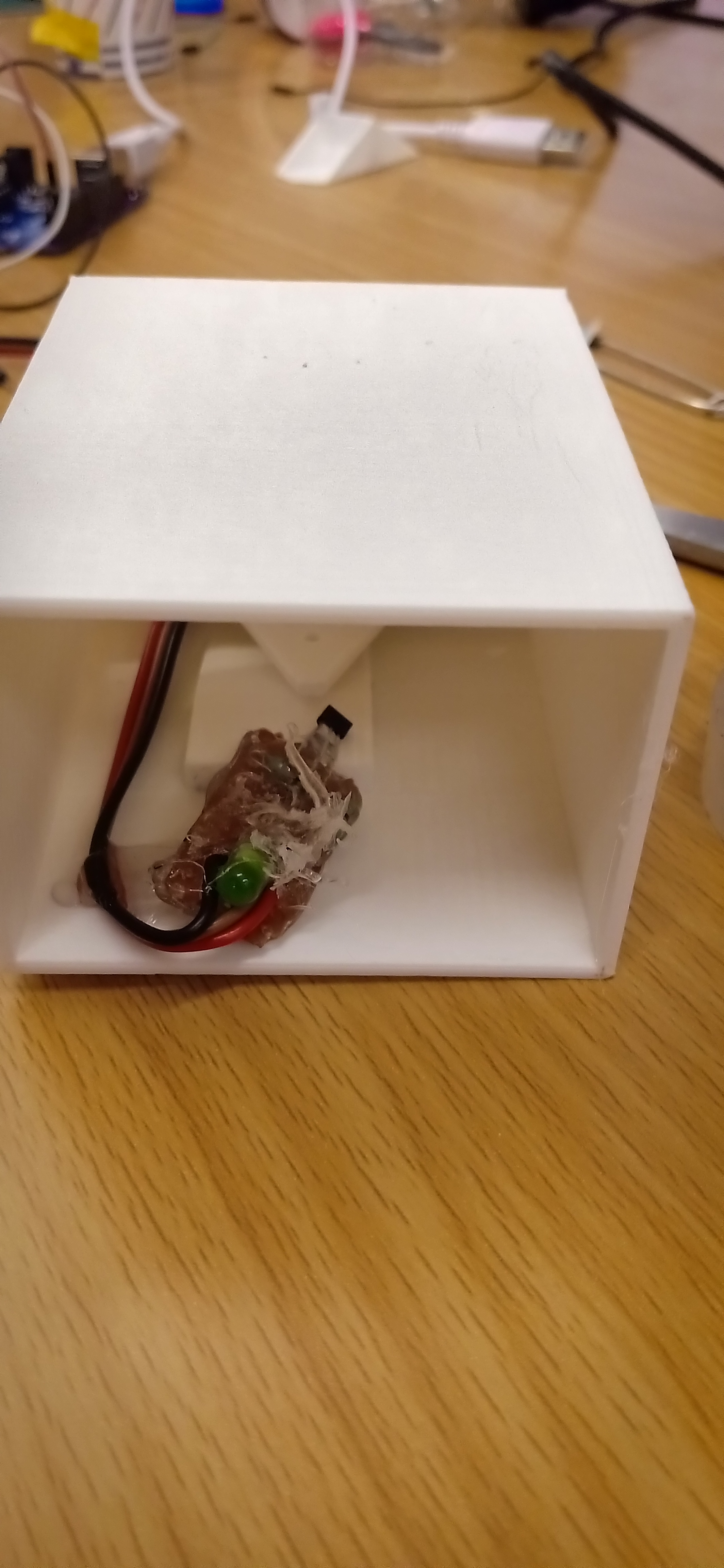
LED- A light emitting diode is a small lightning device made of semi conductor. When it glows , it indicates that the circuit is complete and working.
HALL EFFECT SENSOR- It is a device that senses the presence of a magnetic field and lights up an LED connected to it. (This gives digital results i.e output comes as either high or low)
2 resistors-10Hz , 470 ohms
FUNCTION OF ELECTRIC CIRCUIT
This circuit establishes a relation between the rain gauge setup and the output device.
During rainfall, water falls on the catchment area and gets collected in one of the 2 tipping bucket . When it gets full, it tilts to one side. When it tilts the small magnet attached to it moves. This movement of the magnet is sensed by the Hall effect sensor and the LED ,lights up. We get an output which is recorded in the monitor.