Commercial ceiling fan regulators have been extremely unreliable. While the older ones used triacs, the newer ones merely use a combo of capacitors to divide the voltage being supplied to the motor. If the capacitors are not of excellent quality they will fail resulting in poor speed control. This I have observed happening, but never got around to analysing the capacitor failure mode.
In the case of triac speed controllers most use a 600v Peak Inverse Voltage (PIV) rated triac. PIV is the voltage that the triac can withstand without failure. The mains voltage is 325 Vp. Given that an inductive load is being driven, one should expect a substantially higher momentary back EMF, especially if the firing angle of the trigger pulse is 90^o or 225^o. Consequently a higher rated triac would prove to be more reliable. Also the triacs used seem to be of dubious origin.
Additionally a major irritant is the fan running at a speed set appropriately as per ones comfort and depending on the ambient temperature. As the temperature drops and as our body cools down in the night one often needs to wake up and turn down the speed. this is irritating even during daytime and thoroughly disgusting in the night.
I have long been thinking of making a microcontroller based fan controller. Adding a temperature sensor would be a great boon. I had made a regular triac controller in my old home that worked for 14 odd years, until we left that house.
After the umpteenth failed controller I finally got around to designing one.
Here is the schematic pdf. FanControl.pdf (40.4 KB)
Metastudio does not allow .sch, .pcb, .net, .gbr, .drl files. Lets flag the admins and see if we can change that. @admins
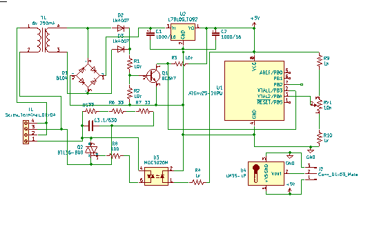
Here is a screen shot of the schematic.
The powersupply consist of a ironcore transformer T1, D1 bridge diode, U2 78L05 linear regulator C1 and C2 capacitors. I have to add 2 ceramic caps to filter out high frequency noise.
The transformer is bulky. Cheap mains powered control circuits use a capacitive divider to reduce costs and bulk. However this is poor practice due to no isolation from mains for the micro and rest of the electronics, it is also a electrocution hazard. Two additional diodes D2 and D3 alongwith the internal diodes of the bridge form a zero crossing detector with transistor Q1. When input voltage is below .6V the transistor stays off. This happens near the zero crossing point. When the voltage rises above .6V the transistor conduct and the collector will go low and remain low until the next zero crossing point. Thus we get a series of high pulses at every zero transition of the AC mains. This pulse is fed to PB3 (pin2 of the Tiny13). The pin is configured as an interrupt pin and will generate an interrupt every 10 ms.
R9, RV1 and R10 provide speed control. The wiper of the pot is connected to pin3 the ADC of the micro. The firing angle will be determined by the position of the pot. LM35 is connected to pin 2 also configured as ADC (error in schematic). This will change the speed depending on the temperature. An over ride button needs to be added. A few LEDs to indicate on and override would also be needed.
The trigger pulse is fed to MOC3020 opto triac . This is an optically isolated triac that is triggered when the internal led is turned on. This is connected to gate of Q2 BT136. R5, R6 R7 and C3 form the snubber circuit to quench high voltage spikes generated when the firing angle is not at 0^o. 3 resistors are used because the resistors are rated for probably 125 volts. A single resistor will arc and fail as the peak mains voltage is 325 volts.
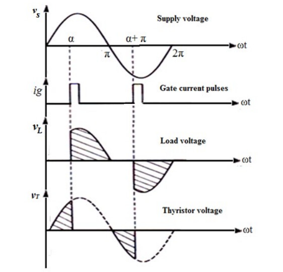
Phase angle control waveforms
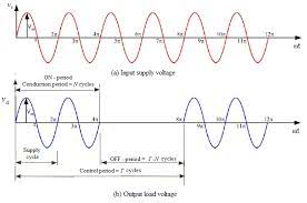
A second technique to control speed is integral cycle control. In this method we turn on the power a few cycles then turn it off for a few cycles. The fan speed will vary as per the ratio of the on time to the cycle time t_{on}/t_{on}+t_{off}. If we take 10 mains cycles as our total period our speed will change by 10% per cycle. The advantage of this method is that we can switch the triac on /off at the zero crossing point. This results in nearly zero Radio Frequency Interference due to there being no steep rise or fall in current and voltage. This steep rise/fall is denoted by {d_i/d_t} for current and {d_v/d_t} for voltage.
The circuit in the previous post remains the same. Only the software will change. We could also use a zero crossing opto triac which will simplify the code a wee bit.
We should take care to switch off only on even number of zero crossings. Ie if our triac turn on is considered the zeroth zero crossing pulse we will switch off at either 2, 4, 6…18. Remember we have 2 zero crossing pulses per cycle - 20 pulses for 10 cycles. If we switch off on an odd pulse, we will have a half cycle ie 325 VDC. Having a DC component in an AC motor appliance is bad. It will damage the appliance. In our case it will result in heating of the fan and eventual failure. Integral cycle control does produce a small residual DC even when the above condition is met, however it is below 1.5%.
Image from https://www.philadelphia.edu.jo/academics/mlazim/uploads/chapter06.pdf. This link provides a very detailed explanation with a whole lot of trigonometry for those interested in knowing all the maths in a humble ac motor.
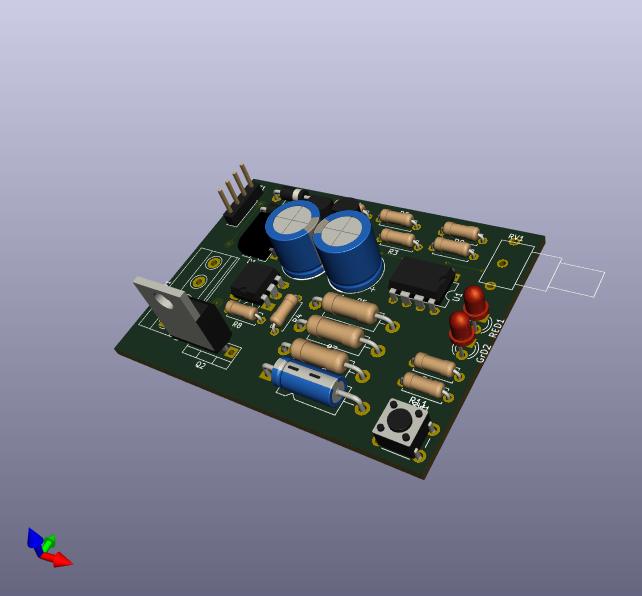
The standard cutout for a regular 5A socket is 50mm vertical x 47mm horizontal. The designed pcb is 46.7 x 62.7. 12.7 mm too large in one dimension. Also the pot should be mounted in the center of the board so that the board can mount on the back of a dummy socket cover. Reducing the board size by 12.7mm seems to be difficult.
Consequently we will have to mount the board horizontally, projecting the 62.7mm length inside the switch board. Therefore the pot will have to be mounted in the middle of the 46.7mm side towards one edge. This change looks feasible as the pot is already quite close to the desired location. We will also have to use a vertical switch with it’s knob projecting outwards and bend our LEDs by 90^o so that the light shines outside. We could use a light pipe - a piece of bent acrylic with the edges heat polished - if we dont want to bend LEDs. Heat polishing is nothing fancy. Just run a hot air gun along the edge for a few seconds. Or gently and quickly move the barrel of a hot soldering iron on the edge.
Light pipes can be used to make very pretty looking displays - Name plates, audio level displays, wall clocks etc.
Mounting the pot on the pcb enables using the pot as a mount point to hold the board to the dummy plate. However I personally do not like this as the pins of the pot are likely to break if you open your switch board a couple of times. I prefer to use a L plate fabricated from pvc or polycarbonate. Metal can be used too, but poses a hazard of coming in contact with a stray wire in the messy insides of a switch board. Which brings up yet another question.
Can we design a switch board without all the messy wiring?
@Farhan has already designed a relay board. Let's design IR control Board
Can it be used in a standard switch box? Will we need a hybrid with part microcontroller+relays and part regular switches? Or should we just get rid of the switches?
We already have zero crossing detection. In principle switching the relays at zero cross will extend it’s life to the maximum as there will be no arcing at the contact point. Which means the relays would last longer than the building.
What would you as a user want in such a microcontroller conrolled switch board?
Remotes?
App control?
Automation via RPi using sensors?
Capability to talk to solar MPTT controller / Battery backups?
Metering?