Yesterday our induction heater stopped working.
I opened the gadget.
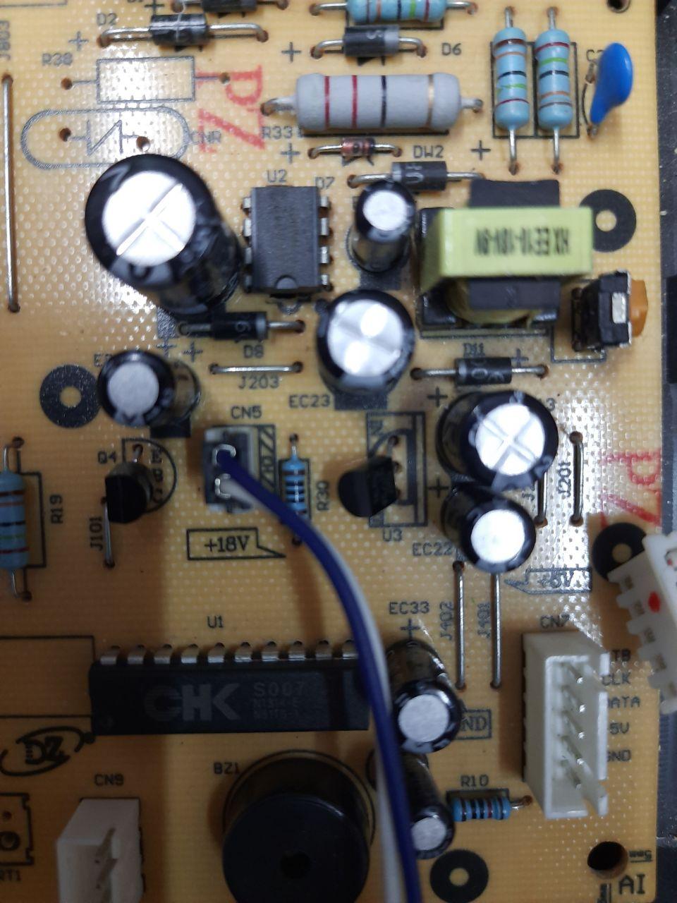
Inside is a 18V SMPS with a 78L05 series regulator. The 78L05 is a lower output current version of the 7805. 78L05 can supply only 100mA. Ideal for powering a microcontroller.
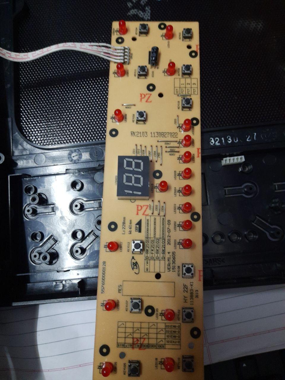
Some images of the main board and keyboard. The microcontroller is a special device built for induction heater control. I could not locate any specs. However the keypad and LED display is driven by a peripheral chip SM1668 whose specs are available. The SMPS uses AP8012 SMPS controller with a built in power mosfet.
The symptom: on power on the keypad lights up and then switches off, which is it’s normal behaviour. When one pushes the on/off tactile push button the device turns on. Pushing it again turns it off. However the device fails to turn on when this button is pressed.
I suspect a powersupply overload causing power to microcontroller to shut off.
The mains remains connected whether on or off - a very bad design aimed at cost cutting. A decent circuit will have a relay that cutsoff power. Or atleast a mains switch. One will have to be very careful while trouble shooting to prevent a nasty shock or a fire.
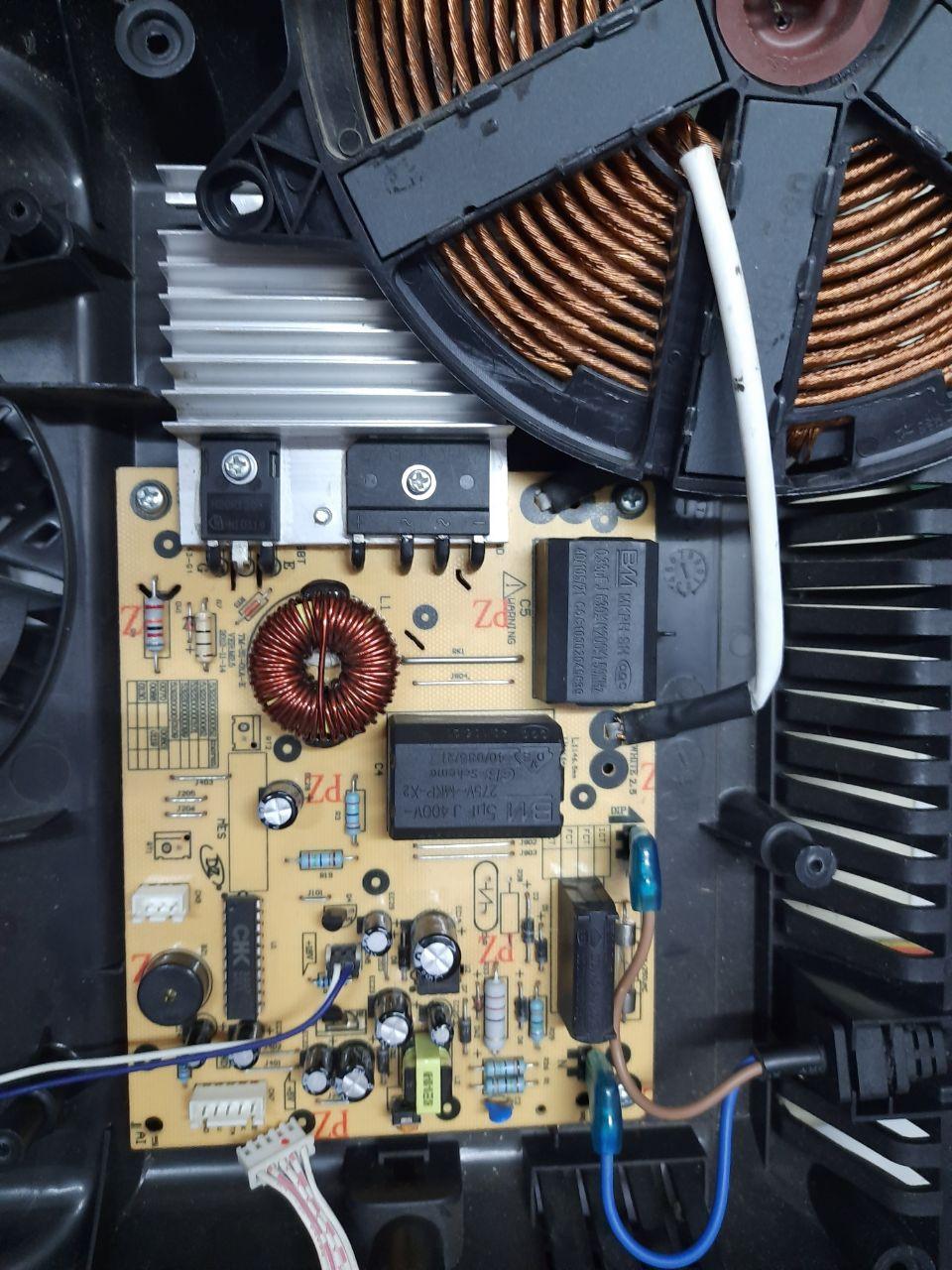
The induction coil drive circuit is intact. No fuse blown. This is a very high powered stage. The IGBT (3rd pic top left black object attached to Al heat sink) and bridge rectifier (right of the same heat sink) are rated at 20 Amps 1200V. If anything goes wrong the fuse is most likely to blow.
So, that is the good news.
To check without the danger of the always on mains, hook in an external 5v to the board. The microcontroller works. The keypad is intermittent. Pressing on/off starts the gadget after a lot of tries.
Remove the external psu and connect the gadget mains. One must be extremely careful now.
Switch on. Same behaviour. the output voltage from the SMPS is 18V. 78L05 provides 5v. So nothing wrong with SMPS.
Inability of witch to operate could be due to bad push button or a wiring problem.
Checking the switch shows that is is ok.
Check the wires with DMM (digital multi meter). Wires check ok.
However I discover a new issue. Which is that the board works when held in a particular position. This means that the wire cable is a probable intermittent open and makes contact in a particular position. Several hours of manipulating the wire cable fails to show anything conclusive. I decide to change the cable. However the connector on the cable is of a different type which I dont have.
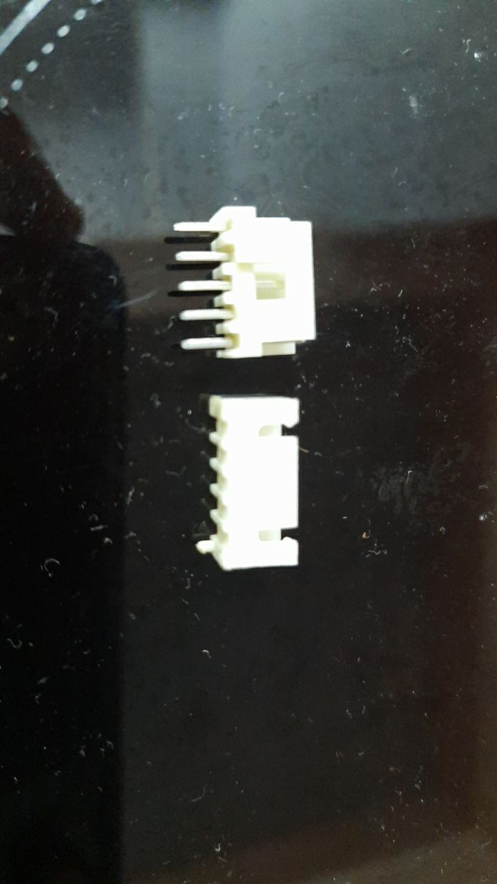
The bottom one is the original. The top one is the replacement. Both have the same pitch and foot print.
Notice the missing pins on the original? Desoldering a rigid multi pin component having more than two pins is most likely to damage the PCB. Especially plastic components. With connectors we can insert a small screw driver under the plastic and lift it off the board. We can then desolder one pin at a time. That is what was done, hence the missing pins.
Having replaced the connector and cable we expect the circuit to work.
It did not and continues to display the same intermittent position dependent operation. This time we are 100% sure about our cable and connector.
Definitely not. Apart from a general use safety point, during trouble shooting me must disconnect the mains.
Depends on the type of fuse. Most daily use fuses are in a transparent glass tube. We will see a black shiny deposit inside the tube if the fuse is blown. This is caused by large fault current causing the fuse wire to melt and explode with splatter. However often the fault might cause the fuse to melt much slower and merely break without any splatter. In such a case we have to either try and see the thin wire or use a multimeter’s ohms range to check. A good fuse will show a short.
The fuse prevents a fire being caused under a fault condition. High current flows caused by component failures produces extreme heat. This can set afire wire insulation and anything else that happens to be in contact. A fuse ruptures in a few seconds when it’s rupture current is reached. Note that the operating current is far lower than the rupture current. A 1A fuse does not rupture at 1A but at a substantially higher current, usually at 250%. Also a 1A fuse is operated at 70% i.e. .75A. IF you do operate it at 1A it will blow perhaps after several hours of use.
Fuses are also of different rated speeds- superfast, fast, slowblo, normal, PTC. PTC fuses do not normally rupture but provide a high resistance until the current drops substantially and the PTC fuse cools.
Fuses have a maximum rated voltage. You can operate below the rated voltage, but never above.
Continued investigation leads to the conclusion that the specific position one holds the board at results in the wire running parallel to a set of tracks. These tracks carry 3 communication signals from the wire to the IC. But the flow of current in the pcb tracks and consequently any electromagnetic field is opposite to that of the wire. Let me try some ascii art to illustrate
[right]"----------------------------------------------------|[/right]
[right] |[/right]
[right] _____________| [/right]
[right] __________[/right]
The top line and the vertical line is the wire. The middle continuous line is the pcb. The bottom continuous line is the pcb track to which wires are soldered. Imagine current flowing in the wire from left to right and onto the track. In the track due to our positioning current is flowing from right to left. Therefore the current set up a a magnetic field in one direction and on the track in the opposite. If we bring them close together - as we are - the two fields should cancel, thus cancelling the interfering current. Thus any unwanted electromagnetic interference gets cancelled and the circuit works.
The above is wholly speculative, but the only explanation I can think off. Given the length of wire and track this interference is in the 800Mhz and above band. The source of such interference is wholly unknown.
One method of eliminating such interference is to shield the wires. There are special wires made with an outer braid of wire or Al foil that acts as shield. Instead of again removing the wires and replacing with a shielded cable, I wrapped a piece of Al foil around the wires and grounded it by connecting an extra wire with a crocodile clip to ground. I was fairly sure that the circuit should now work. Nope. The circuit with cable shielded with Al foil now failed to operate in any position.
So, the malfunction was due to cross coupling interference between wires - signal on one wire interfering with a neighbouring wire. But why did this the cross coupling start after 3 years of use?
I decided to solder the signal wires directly to the IC pin, instead of their current closely spaced position.
First signal was STROBE. This signal enables or disables the keyboard. I soldered it directly to a convenient point near the IC, which is about 4 cm nearer than it earlier point.
VOILA. Everything works just fine.
I packed up the gadget and returned it to the kitchen where it is functioning normally for the last 2 hours.
But this repair almost had me believing in ghosts in the circuit ;-). While the problem does seem cross coupling, this is a design problem and should manifest itself at the design stage, or if it is just marginal, as intermittent malfunctions on the production line, resulting in higher reworking and/or rejections.
There is also this rare chance of some set of components in this specific piece have deteriorated just marginally to cause the problem. In which case we should have a repetition of the problem after a few weeks of operation…