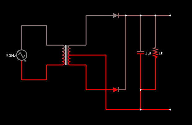
Fullwave circuit. lushproject has a center tapped transformer. You can add a slider to each component by right clicking on a component and selecting slider. You can change the max and min values.
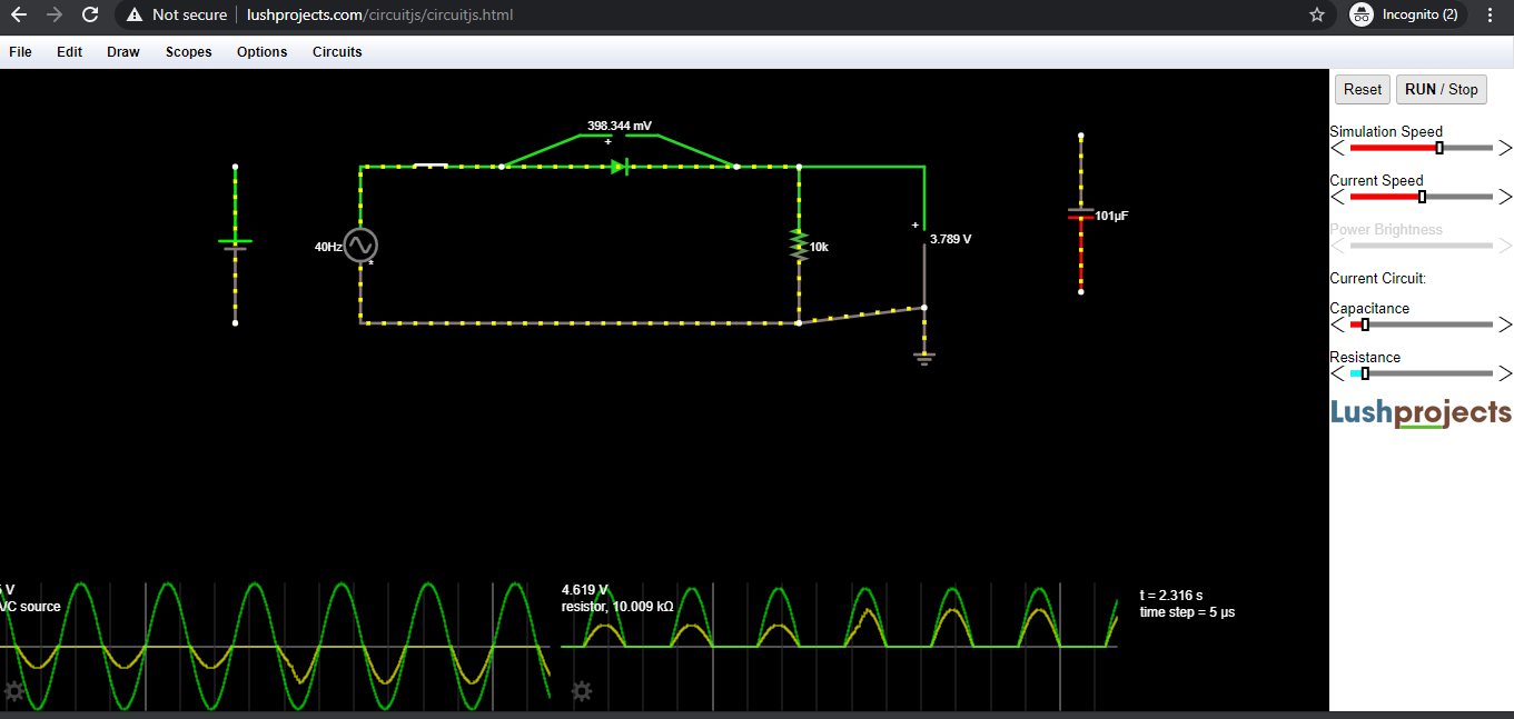
NOTE: Capacitor value for the slider is in Farads. Electronic capacitors are in the pico to micro range (except for the new supercaps used as coincell replacements). Change the value to microfarads.
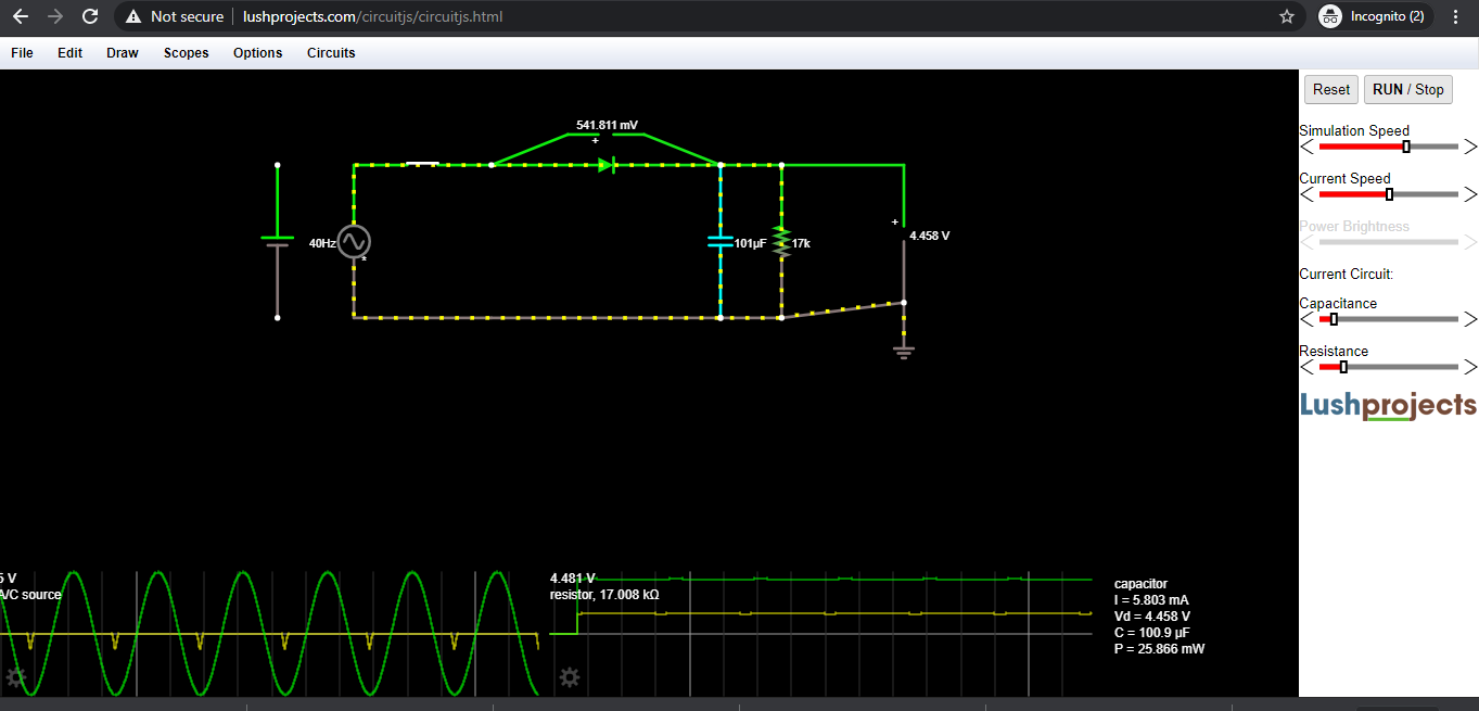
Check the waveforms using scope in the simulator.
Today’s session was really interactive and boosted the confidence to try out circuit changes without the fear of damaging any component, sounding dumb whilst asking doubts and suggesting changes. At the end of the session we left with an open question of how to get an output with both positive as well as negative cycles of signal visible, like in the case of full wave rectifier with 2 diodes…
I tried out this solution, where I connected 2 voltage supply sources, with opposite polarities, same resistance in series with the two but two diodes used here, so that one diode works in forward bias mode during positive cycle of first supply, and other works for positive cycle (as it goes in forward bias mode) of second supply coinciding with the negative cycle of first supply.
As we expect, the opposite supplies should cancel each other out, but the image shows that simulation resulted in our expected output. Now the question is, does this simulation hold true in practical implementation, or not!
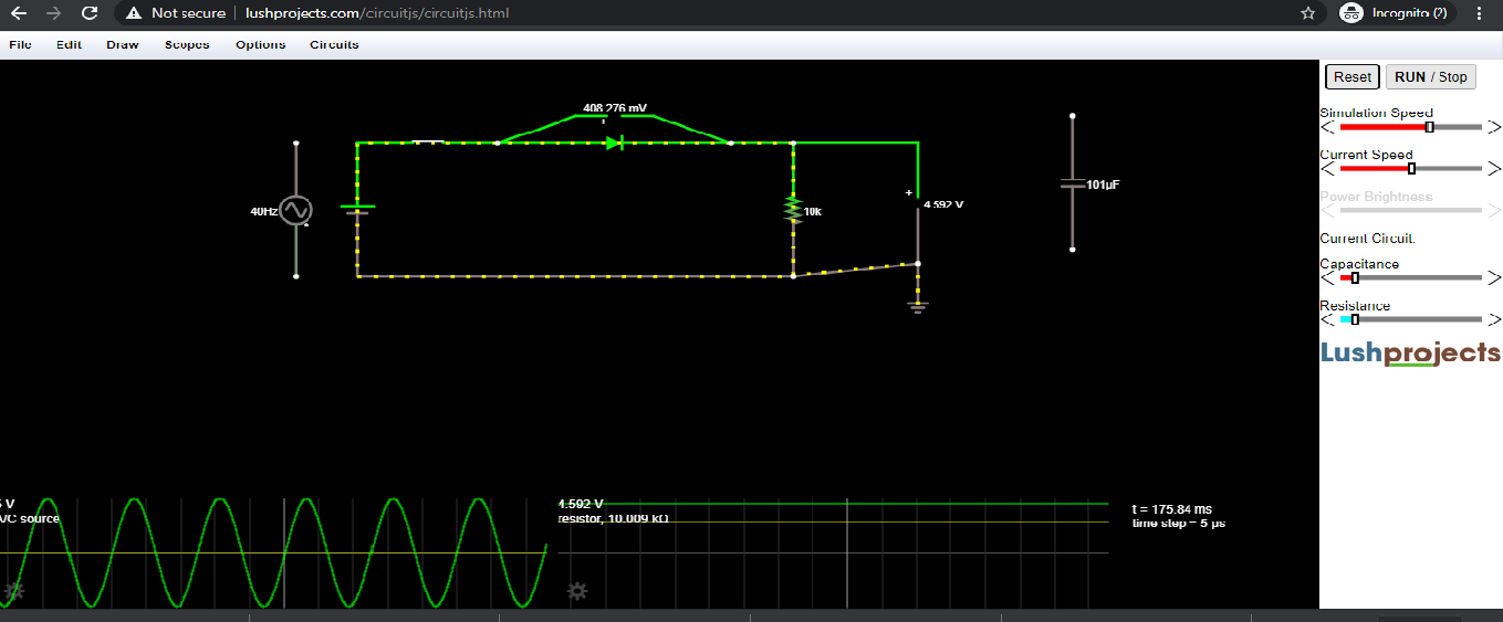
Another interesting find, when tinkering the circuits: Check out the circuit we tried out and see if you (the reader) get the same square waveform! Additionally, let me know whether this will happen for practical circuit too without any damage to the components, or not?