As I have been working on Design and Development of IoT IR Thermometer, In this post specifically i would like to bring the context of designing its 3D encloser, basically will try to understand the FreeCAD workflow and Workbenches.
FreeCAD, an open source software for mechanical CAD. This software provides various workbenches such as Sketcher, Part, Part Design and etc to work on 3D design.
This is the first time i have also explored FreeCAD.
It also has large Community and proper documentation which help a lot to begin with it. One can read more about FreeCAD at the below link:
One can download software as per their operating system from the below link:
To begin with FreeCAD you can also visit the following links:
https://wiki.freecadweb.org/Tutorials
There are also various other Open Source 3D Computer Aided Design (CAD) software available such as OpenSCAD, BRL CAD etc. You can also explore any of these and start working on it.
So coming back to IR Thermometer encloser designing, i have decided to go with gun shape structure for it, although you can also go for some different design structure.
I started with Sketcher workbench of FreeCAD, Where 2D drawing of the shape is drawn first and lator can be padded into 3D body using PAD tool of the Part_Design workbench.
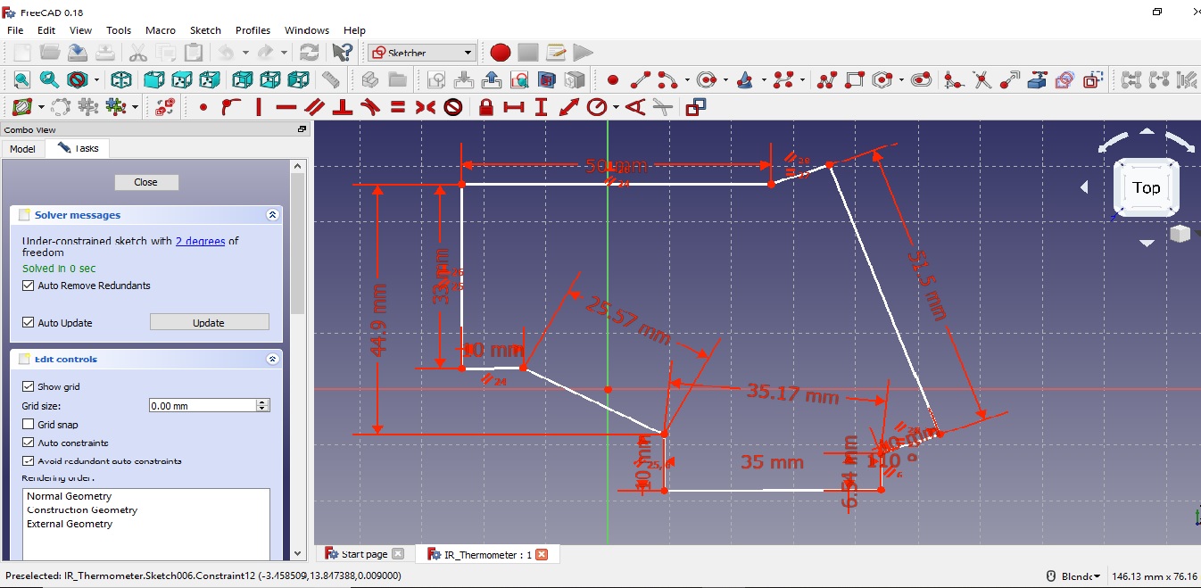
If we carefully observe 2D drawing (aka sketch) you will find that we are in Sketcher workbench and there is proper dimensions defined for each polyline and also each of these polyline is properly constrained using horizontal, vertical, parallel constraints. It is very important to resolve the sketch with constrained with least number of degree of freedom, try to make it fully resolved with 0 degree of freedom.
Now Lets convert 2D sketch into 3D body using PAD tool for which we need to change to Part Design workbench.
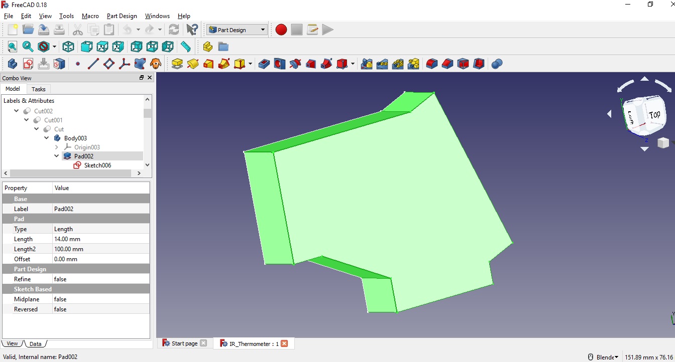
so here we have padded the sketch to 14mm thick 3D body.
Now lets create a pocket to this 3D body for which we again need to draw the sketch for the pocket dimension. We can select any of the face to draw sketch on it.

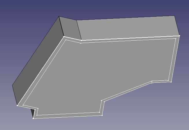
Now lets again use Part Design workbench to actually convert pocket sketch into pocket using Pocket tool.
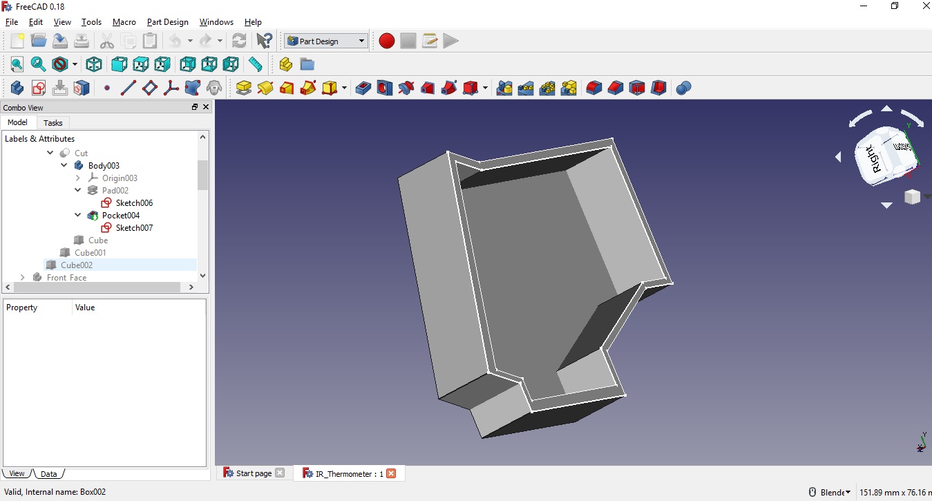
Lets look at the workflow of the design done so far through the Tree-View given in left panel.
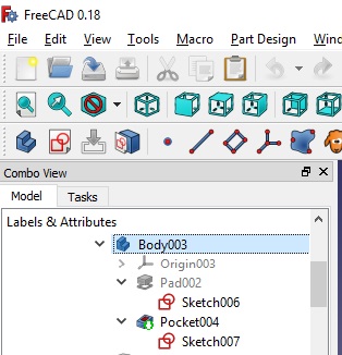
In the above Tree-View Sketch006 is first sketch which is converted into 3D object as Pad002 then Sketch007 is created for making a pocket, which is then used to create a pocket in 3D object as Pocket004. The final body is Body003. We can also rename these sketches and bodies.
As you can see we are working and switching between two workbenches (Sketcher and Part Design) one at a time.
This is the beauty of FreeCAD we can switch to any workbench to take advantage of its tools and facilities.
Now time to work with third workbench ie Part workbench where we can actually add 3D shapes such as cuboid, cone, etc and perform Boolean operations between one or two 3D objects.
Lets also take advantage of Part workbench.

So we have added a cube of required dimension and placed it with left most wall of Body003. The cube is highlighted. Now we will use the boolean cut tool of Part Workbench to cut that wall of Body003.
The resulted 3D object is called Cut, as you can see the Tree-view at left panel of screen.
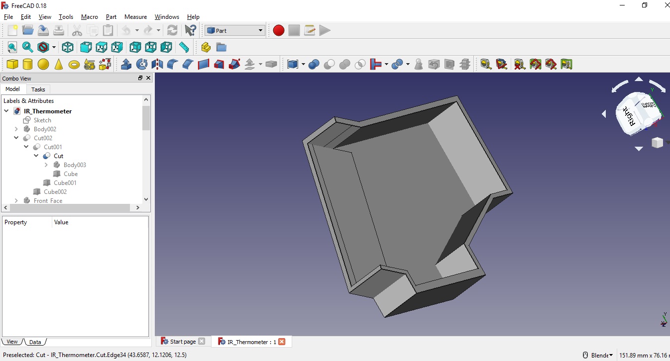
Simillarly we want to cut the right most and bottom most wall.
Adding a cube Cube001
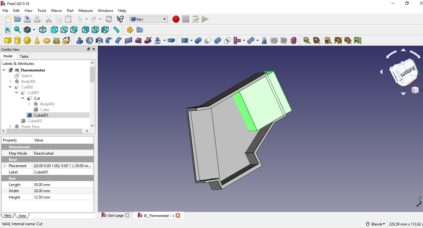
We created 3D Object Cut001

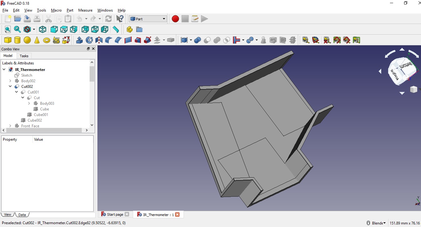
Adding a cube Cube002

We created 3D Object Cut002
Now again lets look at Tree-View of the work done so far.
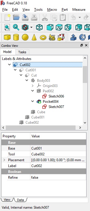
We have already seen the workflow of Body003 and now lets understand the further.
Cutting the Cube from Body003 have made 3D object Cut.
Cutting the Cube001 from Cut have made 3D object Cut001.
Cutting the Cube002 from Cut001 have made 3D object Cut002. Cut002 is the final object designed.
We can also come to this final result without using Part workbench that is only with the help of second sketch (Sketch007) but the described process is mainly for exploring the Part workbench .
So Challenge is: Would you like to modify the Sketch007 to directly get the final 3D object.
I will end this small explanation of the FreeCAD workflow which we have tried to understand with the help of one of the design module of IoT IR Thermometer. I hope it has given you an overview of FreeCAD workflow and its workbenches.
Please do share your work and feel free to ask any query